Supercharge Your Innovation With Domain-Expert AI Agents!

Image forming apparatus with fixing device, the image forming apparatus controlling supply of power to a heater by a driver based on an output of a temperature detector

a technology of fixing device and image forming apparatus, which is applied in the direction of electrographic process apparatus, instruments, optics, etc., can solve the problems of difficult to reduce the size and cost of the image forming apparatus, and the normal operation of the controller may not be secured,

Active Publication Date: 2019-10-15
CANON KK
View PDF5 Cites 1 Cited by
  • Summary
  • Abstract
  • Description
  • Claims
  • Application Information

AI Technical Summary

Benefits of technology

The present invention provides an image forming apparatus that includes a fixing device, a driver, a relay, a temperature detector, a control board, a connector, and a loopback path. The temperature detector detects the temperature of the heater and sends the information to the control board. The control board then controls the supply of power to the heater based on the temperature information. The connector is used to connect the fixing device and the control board. The loopback path allows the applied DC voltage to be directed to the relay as a driving voltage for it. This invention ensures that the image forming apparatus can efficiently fix images on recording materials by heat generated by the heater.

Problems solved by technology

Thus, when the controller is arranged close to the temperature detector, a normal operation of the controller may not be secured due to the heat of the heat-generating element.
When wiring disconnection or other connection abnormalities occur, however, the temperature of the fixing device cannot be accurately detected, with the result that it becomes difficult to perform the temperature control for the fixing device.
Therefore, when all of those components are mounted to the image forming apparatus, it is difficult to reduce the size and the cost of the image forming apparatus.

Method used


Image

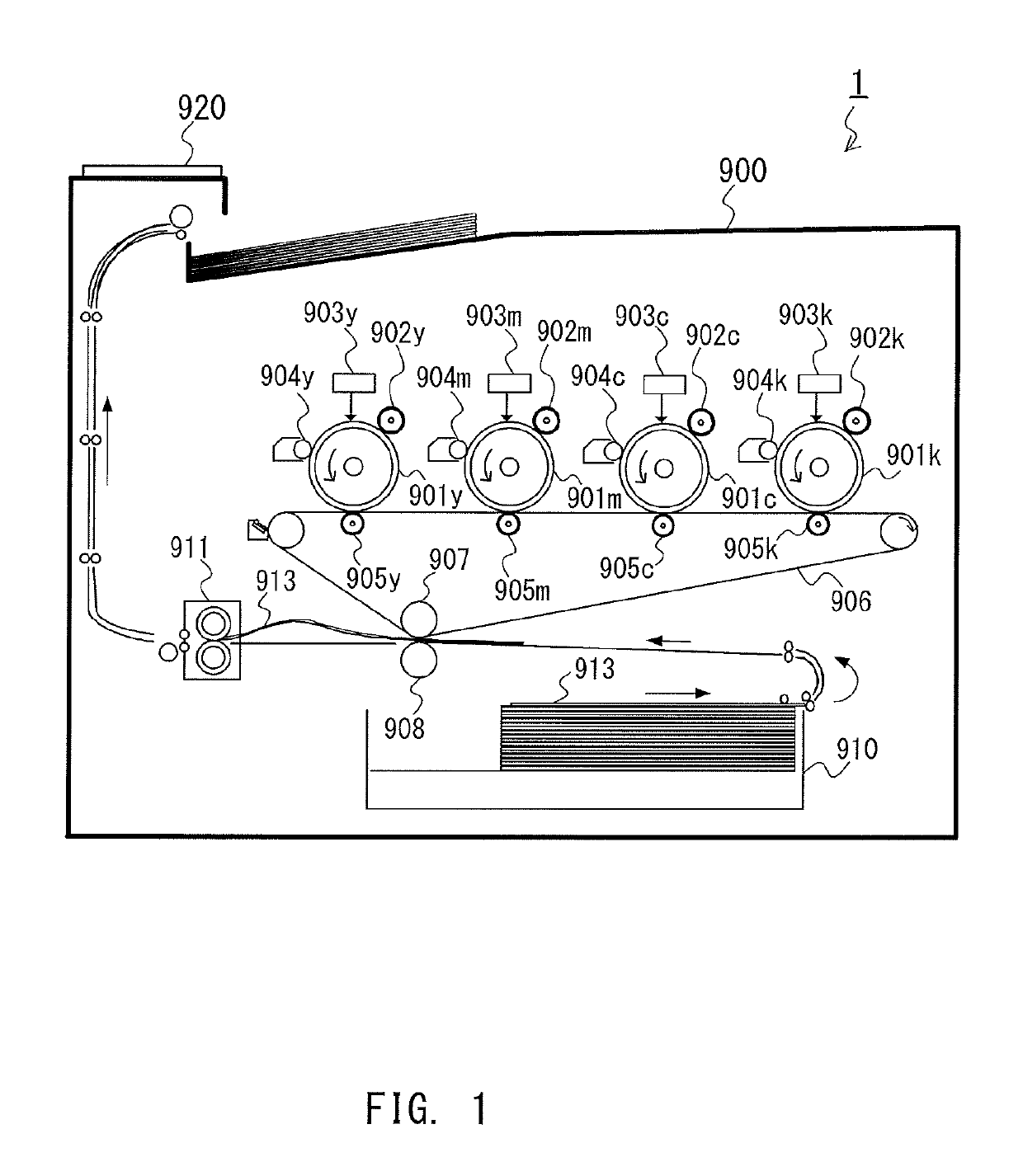
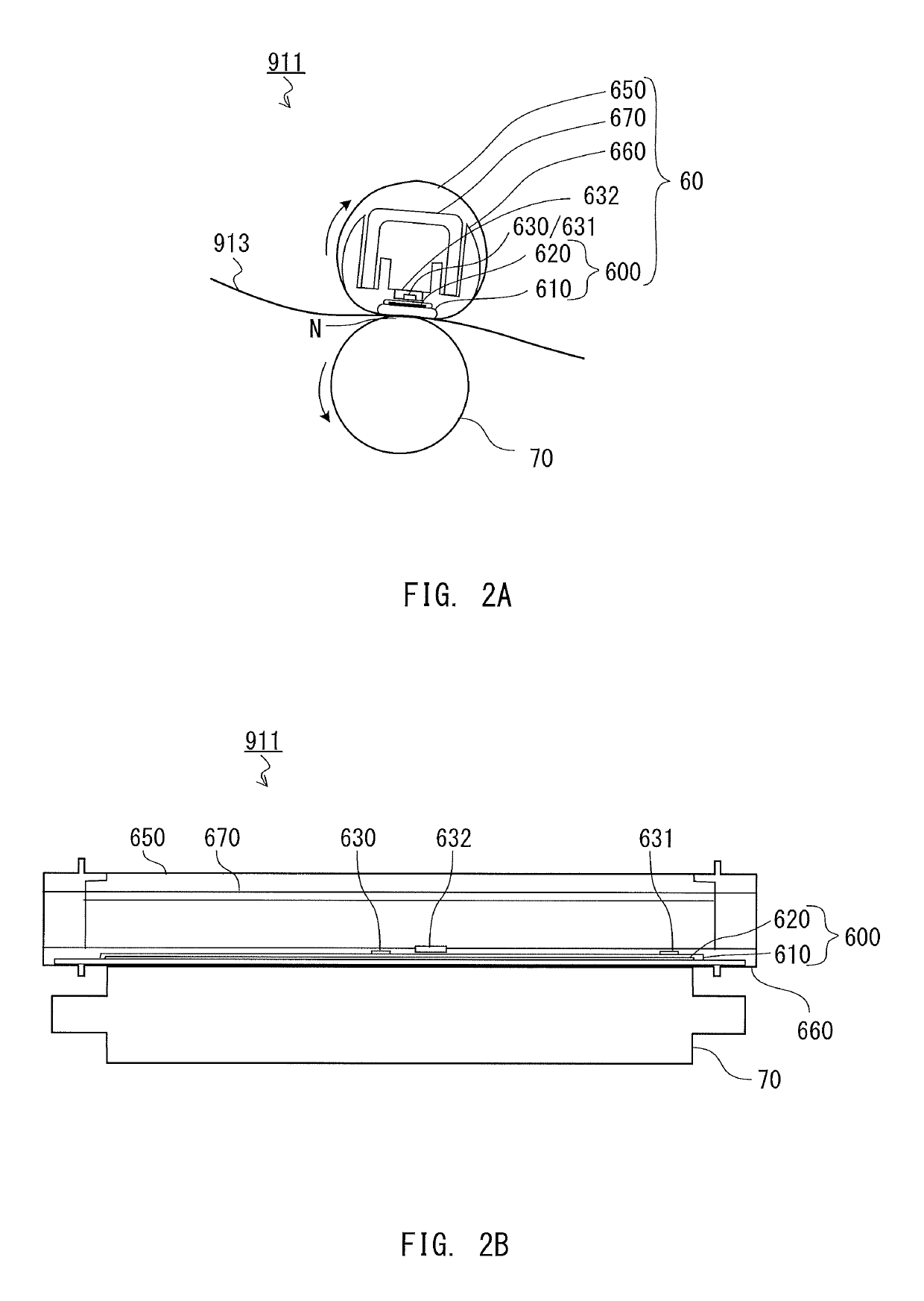
  • Image forming apparatus with fixing device, the image forming apparatus controlling supply of power to a heater by a driver based on an output of a temperature detector
  • Image forming apparatus with fixing device, the image forming apparatus controlling supply of power to a heater by a driver based on an output of a temperature detector
  • Image forming apparatus with fixing device, the image forming apparatus controlling supply of power to a heater by a driver based on an output of a temperature detector

Examples


first embodiment

[0035]Fixing Temperature Controller

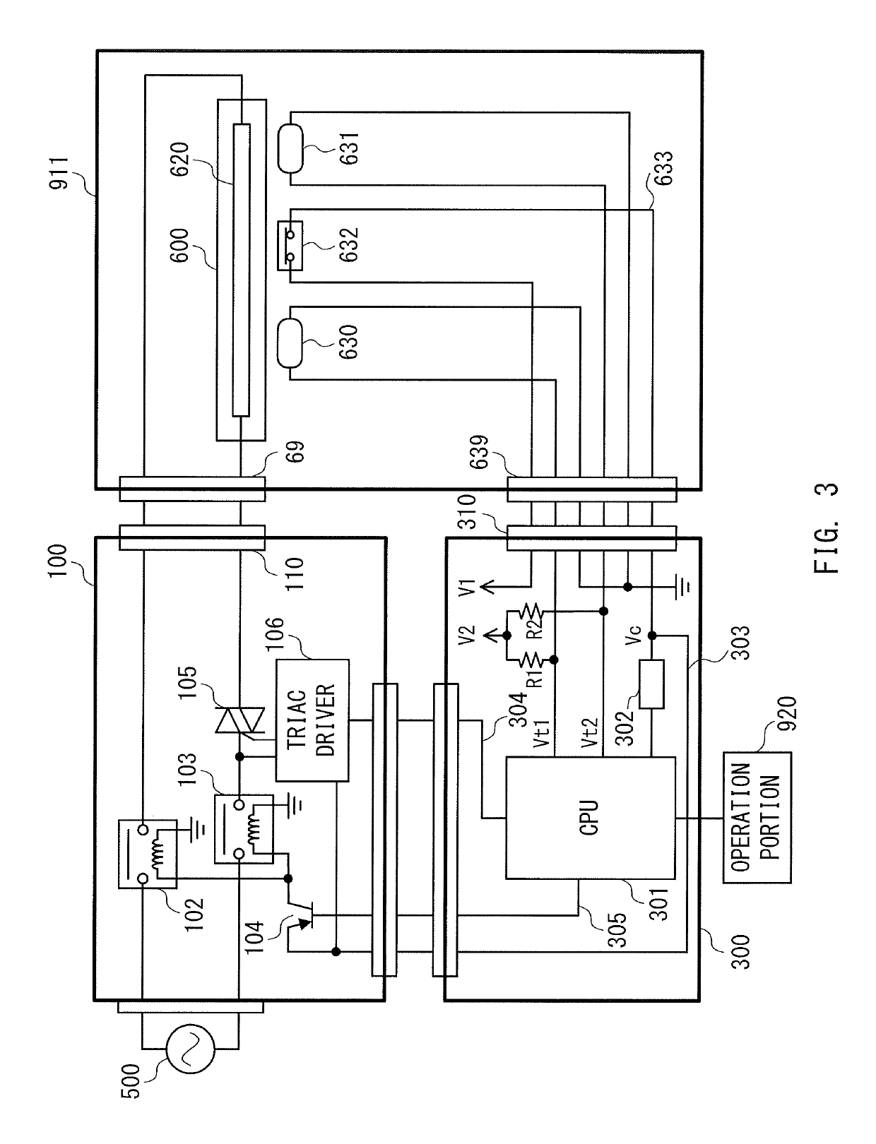
[0036]FIG. 3 is an explanatory diagram for illustrating a fixing temperature controller configured to control the fixing temperature of the fixing device 911. The fixing temperature controller is built in to the printer portion 900. The fixing temperature controller includes a driver board (hereafter referred to as “driver”) 100 and a control board (hereafter referred to as “controller”) 300. The driver 100 applies power supplied from a commercial power supply 500 to the fixing heater 600 of the fixing device 911. The controller 300 performs fixing temperature control for the fixing device 911 and operation control at the time when the printer portion 900 forms an image. The driver 100 and the fixing device 911 are connected to each other by a connector 110 of the driver 100 and a connector 69 of the fixing device 911. The controller 300 and the fixing device 911 are connected to each other by a connector 310 of the controller 300 and a connector 6...

second embodiment

[0068]Fixing Temperature Controller

[0069]The fixing device 911 includes therein a thermistor 634 configured to detect a temperature (fixing temperature), and is connected to a peripheral component (fixing temperature controller), for example, a CPU 701. FIG. 6 is an explanatory diagram for illustrating fixing temperature control of controlling the fixing temperature of such a fixing device 911.

[0070]The fixing device 911 includes the fixing heater 600 as a heat-generating element. The fixing heater 600 is a temperature control target for which a temperature is to be controlled. The fixing device 911 includes the thermistor 634 configured to detect the temperature of the fixing heater 600, and provided at a position in contact with the fixing heater 600. The thermistor 634 is a thermal resistor, and is a temperature detection element having a resistance value that changes depending on temperature. The thermistor 634 in a second embodiment of the present invention is a negative temper...


PUM


Abstract

An image forming apparatus includes a fixing device, a driver, and a relay. A control board controls supply of power to a heater based on an output of a temperature detector. A connector includes a first connection portion to be connected to the fixing device, and a second connection portion to be connected to the control board, and connects the fixing device and the control board to each other. A loopback path is configured such that a direct current (DC) voltage to be applied, via a first terminal of the second connection portion, to a second terminal of the first connection portion is applied to a fourth terminal of the second connection portion via a third terminal of the first connection portion. Further, the DC voltage to be applied to the fourth terminal via the loopback path is applied to the relay as a drive voltage for the relay.

Description

CLAIM TO PRIORITY[0001]This application claims the benefit of Japanese Patent Application No. 2017-169366, filed Sep. 4, 2017, and Japanese Patent Application No. 2017-169369, filed Sep. 4, 2017, both of which are hereby incorporated by reference herein in their entireties.BACKGROUND OF THE INVENTIONField of the Invention[0002]The present invention relates to an image forming apparatus configured, when forming an image on a recording material, such as a sheet, to heat the recording material to fix the image.Description of the Related Art[0003]Some image forming apparatus includes a fixing device configured to heat a recording material to fix an image. Temperature control for the fixing device is performed through detection of the temperature by a thermistor or other temperature detectors. The image forming apparatus includes a controller configured to perform the temperature control for the fixing device by controlling supply of power to the fixing device so that the temperature det...

Claims


Application Information

Patent Timeline
Patent Type & Authority Patents(United States)
IPC IPC(8): G03G15/00G03G15/20
Inventor ISHIKAWA, JUNJIUZAWA, HIROKI
Owner CANON KK
Features
  • R&D
  • Intellectual Property
  • Life Sciences
  • Materials
  • Tech Scout
  • Unparalleled Data Quality
  • Higher Quality Content
  • 60% Fewer Hallucinations
Learn More