Sensing and control arrangements for respiratory device

a technology of sensor modules and control arrangements, which is applied in the field of sensor modules and control systems, can solve the problems of reducing the convenience or increasing the cost of using sensors, unnecessarily increasing the cost of the respiratory therapy system, etc., and achieves the effects of reducing convenience, facilitating the use of closed-loop control systems, and improving model accuracy

Active Publication Date: 2019-10-22
FISHER & PAYKEL HEALTHCARE LTD
View PDF14 Cites 9 Cited by
  • Summary
  • Abstract
  • Description
  • Claims
  • Application Information

AI Technical Summary

Benefits of technology

[0007]Sensors can be used to determine characteristics of gases used in a respiratory therapy system. The determined gas characteristics can be used in the control of various components of the respiratory therapy system. For example, if the gases temperature desired at the end of a gas conduit is 37° C., if the temperature of the gases at or near the end of the conduit can be measured, then the heat output of a conduit heater can be adjusted according to a function of the desired gases temperature and the measured gases temperature to help ensure that the desired gases temperature is achieved. It is desirable to measure gas characteristics of gases as close to a patient using the respiratory therapy system as possible to improve the accuracy of models adapted to control the respiratory therapy system components or to facilitate the use of closed-loop control systems. Transmitting signals from sensors positioned relatively close to the patient to a signal receiver located, for example, at a flow generator upstream of the sensors can require the use of additional wires for data transmission, which can decrease the convenience or increase the cost of using the sensors. If usage of the sensors is not desired, their presence can unnecessarily increase the cost of the respiratory therapy system. Solutions are sought for one or more of the above concerns.
[0008]Certain features, aspects and advantages of at least one of the configurations disclosed herein include the realization that a sensor module may be positioned between components of a respiratory therapy system. For example, the sensor module can be positioned between a gases conduit and a patient interface. The sensor module can comprise a gases inlet, a gases outlet, and a lumen extending between the gases inlet and the gases outlet. The sensor module can also comprise one or more sensors adapted to measure or determine one or more characteristics of gases passing through the lumen. Data signals obtained from the sensors can be transmitted over, for example, wires used to heat the gases conduit and / or energize the sensor module by superimposing the data signals over power signals transmitted over the wires. The sensor module can releasably engage with the components of the respiratory therapy system, allowing for a modular or convenient design. Additionally, because the sensor module is not permanently joined to the gases conduit, the sensor module can be reused.

Problems solved by technology

Transmitting signals from sensors positioned relatively close to the patient to a signal receiver located, for example, at a flow generator upstream of the sensors can require the use of additional wires for data transmission, which can decrease the convenience or increase the cost of using the sensors.
If usage of the sensors is not desired, their presence can unnecessarily increase the cost of the respiratory therapy system.

Method used


Image

  • Sensing and control arrangements for respiratory device
  • Sensing and control arrangements for respiratory device
  • Sensing and control arrangements for respiratory device

Examples


Embodiment Construction

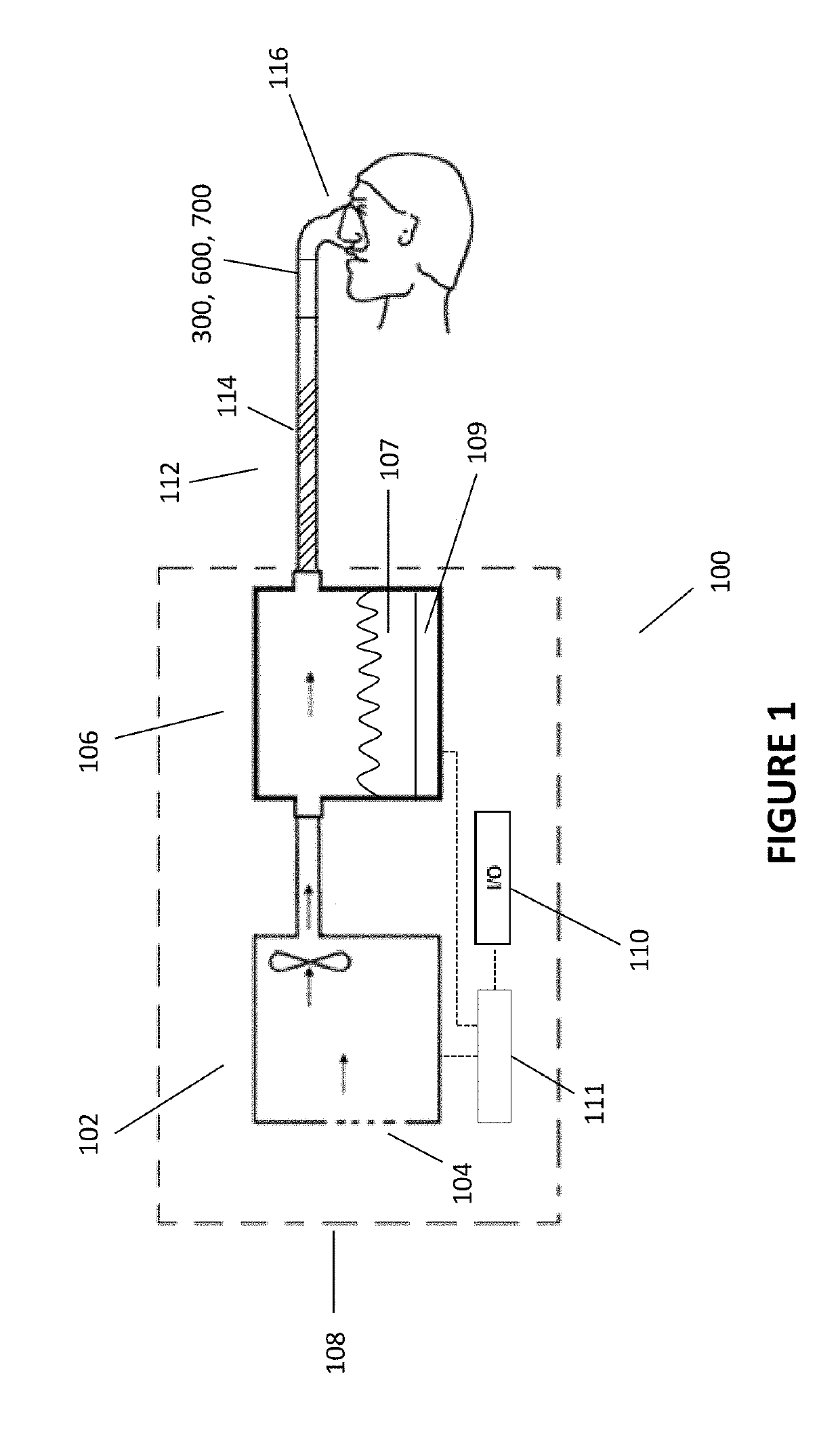
[0017]With reference to the non-limiting exemplary embodiment illustrated in FIG. 1, a respiratory therapy system 100 is shown. The respiratory therapy system 100 comprises a flow generator 102. The flow generator 102 comprises a positive airway pressure or PAP device. The flow generator 102 receives gases from a gases inlet 104 and propels them to a humidifier 106. The flow generator 102 and humidifier 106 may be part of an integrated flow delivery system or may share a housing 108. The humidifier 106 heats and humidifies the gases. The humidifier 106 comprises a quantity of water or another moisturizing agent 107 (hereinafter referred to as water). The humidifier 106 also comprises a heating plate 109 that may be used to heat the water in the humidifier 106 to encourage water vaporization and / or entrainment in the gas flow and increase the temperature of gases passing through the humidifier 106. The heating plate may, for example, comprise a resistive metallic heating plate. Heate...


PUM


Abstract

Various characteristics of a gas flow can be sensed at the end of a respiratory conduit near the patient interface using a sensing module. The sensing module can be removable from the patient end of the respiratory conduit for ease of use and ease of cleaning. The sensor module can transmit sensor data over the same wires used to heat the respiratory conduit.

Description

INCORPORATION BY REFERENCE TO ANY PRIORITY APPLICATIONS[0001]Any and all applications for which a foreign or domestic priority claim is identified in the Application Data Sheet as filed with the present application are hereby incorporated by reference under 37 CFR 1.57.BACKGROUND[0002]Technical Field[0003]The present disclosure generally relates to sensor modules and control systems for use with gas therapy devices.[0004]Description of the Related Art[0005]In patients suffering from obstructive sleep apnea (OSA), muscles that normally keep the upper airway open relax during slumber to the extent that the airway is constrained or completely closed off, a phenomenon often manifesting itself in the form of snoring. When this occurs for a period of time, the patient's brain typically recognizes the threat of hypoxia and partially wakes the patient in order to open the airway so that normal breathing may resume. The patient may be unaware of these waking episodes, which may occur as many...

Claims


Application Information

Patent Timeline
Patent Type & Authority Patents(United States)
IPC IPC(8): A61M16/00A61M16/04A61M16/06A61M16/08A61M16/10A61M16/16
CPCA61M16/109A61M16/0051A61M16/06A61M16/1095A61M16/16A61M16/161A61M16/0069A61M16/0875A61M2016/003A61M2016/0027A61M2205/14A61M2205/18A61M2205/332A61M2205/3306A61M2205/3334A61M2205/3368A61M2205/3375A61M2205/42A61M2210/0618A61M2230/432A61M2230/435A61M2230/62A61M16/026A61M16/0816
Inventor MILLER, JEREMY LIVINGSTONALAMI, NORDYNRHODES, DAVID CHARLES
Owner FISHER & PAYKEL HEALTHCARE LTD
Why Eureka
Try Eureka