Eureka AIR delivers breakthrough ideas for toughest innovation challenges, trusted by R&D personnel around the world.

Superelastic tire

Active Publication Date: 2019-10-22
UNITED STATES GOVERNMENT ADMINISTRATOR OF NASA
View PDF4 Cites 2 Cited by
  • Summary
  • Abstract
  • Description
  • Claims
  • Application Information

AI Technical Summary

Benefits of technology

The patent describes a new technology that uses shape memory alloys to improve the amount of deformation that springs can handle without getting bent or permanently deformed. By using these alloys to create supporting springs, the tires made from them can withstand higher levels of strain without getting permanently deformed. This technology also allows for better control over the stiffness of the springs as they deform, making it easier to design and modify the tires for different conditions.

Problems solved by technology

However, conventional rubber pneumatic tires cannot function acceptably on such surfaces and Space conditions.
Further, rubber degrades when exposed to direct solar radiation, without atmospheric protection.
Finally, an air-filled tire is not permissible for manned lunar vehicles because of the possibility of deflation, e.g., a flat tire.
The original wire mesh design of the Apollo LRV tire was not readily scalable.
Specifically, the increase in wire diameter to create a tire that supported many times the load of the original design created two significant limitations: 1) the ability to contour to the terrain was lost, thus limiting traction and ability to isolate vibration; and 2) the increased wire stress limited functional life.
However, designs based on helical spring constructions using conventional metals (e.g. Aluminum, Brass, Steel, and the like) can be limited when applied.
The constructions exhibited a limited range over which they could be designed to function without undergoing permanent deformation during operation.
This limitation occurred as a result of the helical geometries with conventional metals.
The aforementioned limitations with the helical based architectures result primarily from the use of conventional metals within the design.
Although, the utilization of structures like the spring will aid in allowing more deformation before the onset of plasticity, the utilization of the spring form with conventional metals can cause lower load carrying capabilities due to an increase in compliance.
The helical structures with conventional metals results in tradeoffs due to the limitations of the conventional metal being used.
The additional material can result in an increase in metal volume of almost 500% in certain cases and leads to an increase in the overall mass of the tire, increased production cost, and a reduction in performance.

Method used


Image

  • Superelastic tire
  • Superelastic tire
  • Superelastic tire

Examples


Embodiment Construction

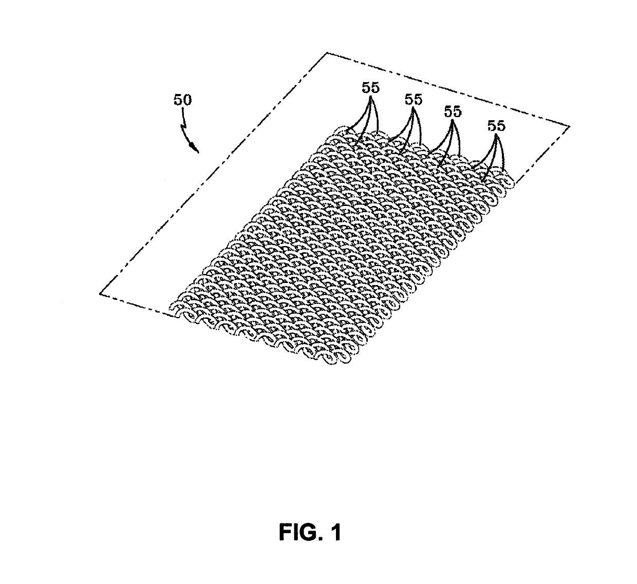
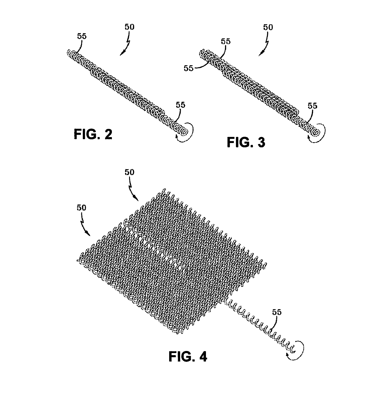
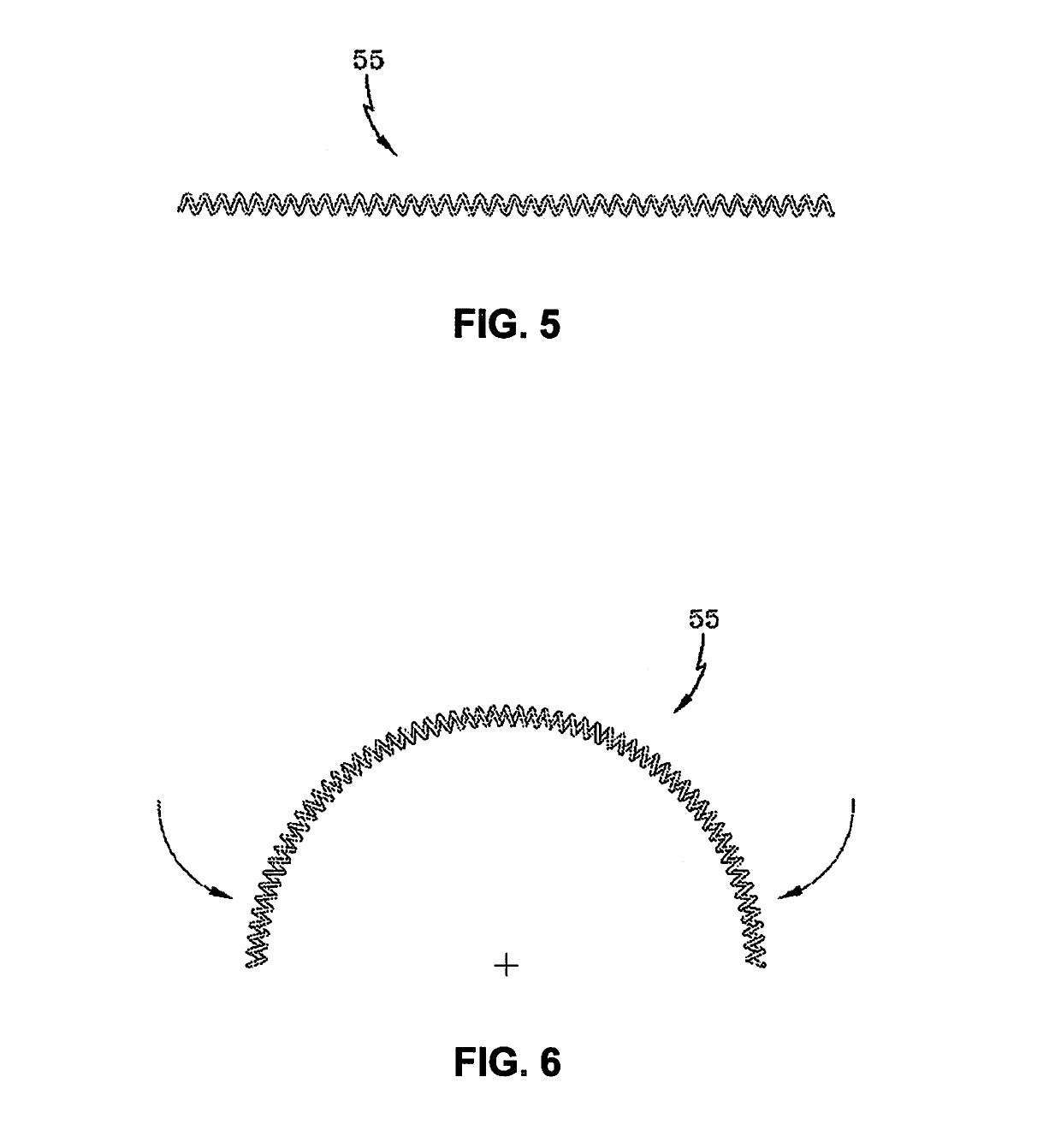
[0026]Embodiments or examples illustrated in the drawings are disclosed below using specific language. It will nevertheless be understood that the embodiments or examples are not intended to be limiting. Any alterations and modifications in the disclosed embodiments and any further applications of the principles disclosed in this document are contemplated as would normally occur to one of ordinary skill in the pertinent art. Described herein are examples of systems, and other embodiments associated with spring tires with superelastic shape memory alloys.

[0027]Shape memory alloys (SMAs) are a class of materials that are not limited to elastic deformation in the design. SMAs undergo a solid-state phase transformation (an inelastic process that happens to be reversible) that allows the SMA to receive up to 8-12% strain before initiating irrecoverable, plastic deformation. The increased strain capability of the SMA material translates to an increase in reversible deformation of the tire...


PUM

PropertyMeasurementUnit
Fractionaaaaaaaaaa
Structureaaaaaaaaaa
Shape memory effectaaaaaaaaaa

Abstract

A tire includes a plurality of SMA springs. Each SMA spring includes a first end portion, a second end portion, and an arching middle portion. Each SMA spring is interlaced with at least one other SMA spring thereby forming a laced toroidal structure extending about an entire circumference of the tire.

Description

CROSS REFERENCE TO RELATED APPLICATIONS[0001]This application claims the benefit of U.S. Provisional Patent application, Ser. No. 62 / 266,183, entitled “Superelastic Tire” and filed Dec. 11, 2015. The entirety of the above-noted application is incorporated by reference herein.ORIGIN OF THE INVENTION[0002]The invention described herein was made by employees of the United States Government and may be manufactured and used by or for the Government for Government purposes without the payment of any royalties thereon or therefore.FIELD OF THE INVENTION[0003]The present innovation is in the field of superelastic materials. The present innovation also relates to a tire.BACKGROUND[0004]Surface vehicles are being developed to support long-range lunar or planetary exploration and the development of a lunar or planetary outpost. The surface vehicles will be heavier and will travel greater distances than the original Lunar Roving Vehicle (LRV) developed for the Apollo program in the late 1960s. ...

Claims


Application Information

Patent Timeline
IPC IPC(8): B60C7/20B60C7/06C22C19/03C22F1/00C22C5/02C22C30/02C22C13/00C22C18/02C22C5/04C22C9/05C22C20/00C22C27/02C22C30/00
CPCB60C7/06B60C7/20C22C18/02C22C19/03C22C30/02C22F1/006B60Y2200/80C22C20/00C22C5/04C22C30/00C22C9/05C22C13/00C22C5/02C22C27/02B60C9/0007B60C7/26B60C15/0216
Inventor PADULA, II, SANTO A.BENZING, JAMESASNANI, VIVAKE M.
Owner UNITED STATES GOVERNMENT ADMINISTRATOR OF NASA
Why Eureka
Eureka Blog
Learn More