Hinged lens configuration for a compact portable head-mounted display system

a display system and lens configuration technology, applied in the field of compact portable head-mounted display systems, can solve the problems of affecting the image quality of the display module, and the weight of the device is far forward, so as to achieve compact and comfortable wear, enhance the effect of hmd and enhance the image quality

Active Publication Date: 2019-10-22
SHARP KK
View PDF54 Cites 0 Cited by
  • Summary
  • Abstract
  • Description
  • Claims
  • Application Information

AI Technical Summary

Benefits of technology

[0009]There is a need in the art, therefore, for an enhanced HMD system that is compact and comfortable to wear, without sacrificing image quality as needed for optimal VR and AR applications, and that further is readily portable and stored. The present invention provides for HMD configurations that are light weight and comfortable for viewing, with high image quality and a wide field of view (FOV). In addition, embodiments of the disclosed HMD system permit a compact foldable HMD system to realized. HMD configurations are disclosed that solve the existing problems of limited portability by allowing the optical components, rather than simply frame or housing components, to be foldable. In this manner, high image quality is achieved in a non-smartphone configuration with reduced form factors comparable to drop-in smartphone systems.
[0010]Regarding the overall form factor, the HMD system of the present disclosure improves the compactness of the system while using a folded optical arrangement. Configurations of the HMD system employ a combination of image panels that are on the eye or viewing side of the eyepiece lenses, close to the head, and also image panels that are on the image or non-viewing side of the eyepiece lenses. An advantage of such an arrangement is that the HMD system protrudes from the face for a distance less than previous designs, and therefore can have significantly reduced weight, be much closer to the face, and hence produces less fatigue while wearing. The design also means near-eye optics can be used to give a large FOV, but also allows space for the user's nose to provide a more comfortable configuration to wear.
[0012]The described configuration has an advantage in that there is as little unseen area on the image panels as practicable, which minimizes the form factor of the HMD system. In addition, with such configuration the optical arrangement allows plenty of room for the user's nose. Furthermore, the weight is concentrated closer to the user's head, so the torque on the head and neck is reduced, and the conventional requirement for a strap to wear the system becomes less necessary. The result is an enhanced HMD system that is compact and comfortable to wear, without sacrificing image quality as needed for optimal VR and AR applications.
[0013]In addition, optical components themselves form part of a hinged configuration along which the HMD system can be folded when not in use. The hinged configuration may be combined with any HMD configuration including multiple image panels and / or or segmented eyepiece lens components. An advantage of this hinged configuration is that a user can fold the HMD system for ease of storage and transportation while maintaining a high level of image quality during use.
[0015]As defined with reference to the HMD system, a z-axis points in a direction from the user to the HMD system, and x- and y-axes follow a right hand rule convention. With directional axes so defined, an axis of rotation for foldable optical components of each eyepiece may be about the y-axis in exemplary embodiments. An axis of rotation for foldable optical components of each eyepiece may be about the z-axis in alternative exemplary embodiments. Having separate optical pathways with different eyepiece lens components and image panels allows the different optical component segments of the HMD system to be rotated with respect to one another so that the optical component segments can be separated and realigned conveniently. This principle could be applied to any configuration of an HMD system having segmented lens components within a respective eyepiece, and / or multiple image panels. In this manner, the HMD system of the present disclosure is highly portable for easy storage and transport while maintaining a high level of image quality during use.

Problems solved by technology

Furthermore, the weight of the device is far forward when worn, meaning that long term viewing could become tiresome on the face and neck due to the torque generated about the head by the weight of the device.
Such optical configuration requires substantial space between the eyepiece and the display module.
Furthermore, complex lenses are needed if the HMD needs to display images with high quality and a wide field of view (FOV).
The result of these requirements in conventional systems is a heavy and bulky headset that is uncomfortable to wear for any length of time, and the size is limited by basic optics to achieve the correct magnification and the virtual image distance.
Due to the bulkiness of conventional configurations, portability has become an issue in that conventional HMD systems take up substantial space for storage and transport.
Many such systems are not foldable and have a fixed form factor.
The benefit of portability, however, is generally offset by the lower image quality of drop-in smartphone type HMD systems.
Although such a system reduces the overall form factor during use as compared to prior conventional configurations, in this initial design the form factor is fixed and therefore the reduction of the form factor during periods of non-use, such as for storage and transport, still have been limited by the optical requirements of usage.

Method used


Image

  • Hinged lens configuration for a compact portable head-mounted display system
  • Hinged lens configuration for a compact portable head-mounted display system
  • Hinged lens configuration for a compact portable head-mounted display system

Examples


Embodiment Construction

[0029]Embodiments of the present invention will now be described with reference to the drawings, wherein like reference numerals are used to refer to like elements throughout. It will be understood that the figures are not necessarily to scale.

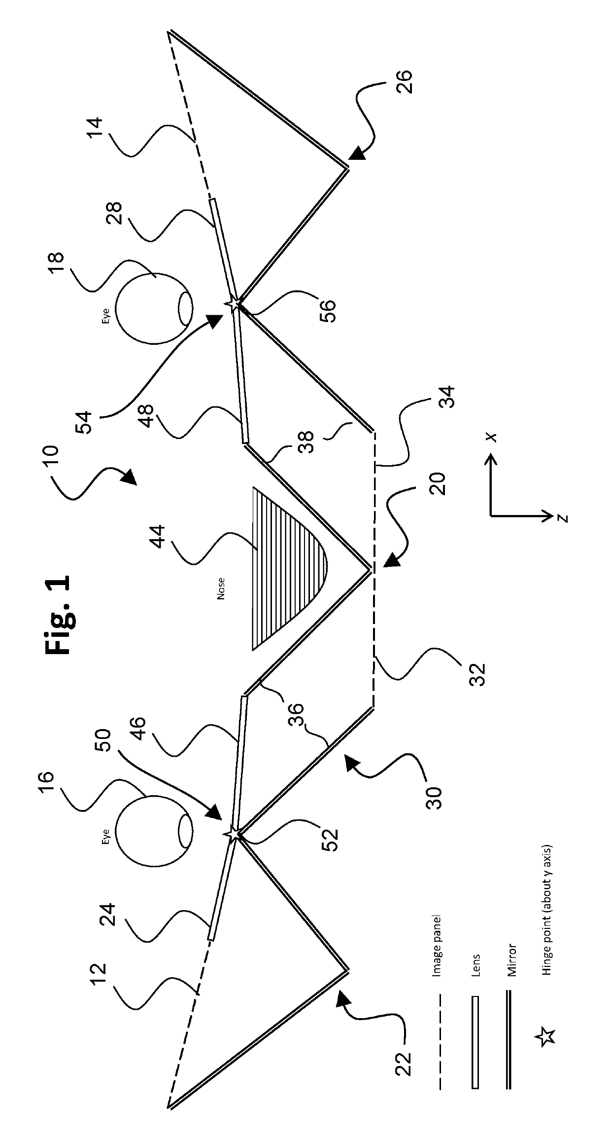
[0030]FIG. 1 is a drawing depicting a top view of an exemplary head-mounted display (HMD) system 10 in accordance with embodiments of the present invention, with the HMD system being in an unfolded state. In exemplary embodiments, the HMD system includes three image panels, which may be of equal dimensions. Referring to the figure, a first image panel 12 and a second image panel 14 are respectively used to present an image in an unshared fashion to each of the right eye 16 and the left eye 18 of a user. The HMD system 10 further includes a third or shared image panel 20 that is located centrally relative to the first and second image panels, and the third image panel 20 presents an image that is shared between both left and right eyes. In this...


PUM


Abstract

A head-mounted display (HMD) system includes an optical arrangement, a first image panel, a second image panel, and a central image panel located between the first and second image panels. The optical arrangement is reconfigurable between a first position and a second position that maintains first and second optical pathways of the first and second image panels, and the HMD system has a different form factor when the optical arrangement is in the second position as compared to the first position. The optical arrangement includes at least one segmented optical component, wherein segments of the segmented optical component are moveable relative to each other to reconfigure the optical arrangement between the first position and the second position. The segmented optical component may include one more lens assemblies, each with multiple lens segments that are rotatable relative to each other about a hinge structure.

Description

TECHNICAL FIELD[0001]The present invention has application within the field of compact wearable displays, and in particular, head-mounted display (HMD) systems used for applications such as virtual reality and augmented reality.BACKGROUND ART[0002]A head-mounted display (HMD) system is a type of wearable device with increasing popularity within the consumer electronics industry. HMDs, along with similar devices such as helmet-mounted displays, smart glasses, and virtual reality headsets, allow users to wear a display device such that the hardware remains fixed to their heads regardless of the user's movement.[0003]When combined with environmental sensors such as cameras, accelerometers, gyroscopes, compasses, and light meters, HMDs can provide users with experiences in virtual reality and augmented reality. Virtual reality (VR) allows a user to be completely submerged into a virtual world where everything the user sees comes from the display device. Devices that provide augmented re...

Claims


Application Information

Patent Timeline
Patent Type & Authority Patents(United States)
IPC IPC(8): G02B27/01G02B17/00G02B27/00
CPCG02B27/017G02B17/004G02B27/0081G02B17/008G02B27/0172G02B27/0176G02B30/37G02B2027/0123G02B2027/0134
Inventor TAM, KA HOMONTGOMERY, DAVID JAMESWELLS, SCOTT
Owner SHARP KK
Why Eureka
Try Eureka