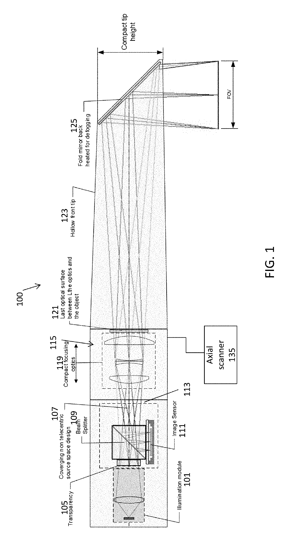
[0010]For example, the portion of the optical system between the beam splitter and the front tip can be configured small enough to be disposed entirely into the depth scanning module. Therefore, the apparatus confocal scanning can comprise a single opto-mechanical module for imaging and depth scanning. The single optomechanical module integrating the optical system and the depth scanning module can leads to relaxed production and assembly tolerances as well as reduced manufacturing cost. The optical design is suitable for LED illuminated transparency, which further enables low cost manufacturing. The optical system can further comprise reduced number of lenses, for example, the optical system can comprise less than 10 lenses, less than 9 lenses, less than 5 lenses, less than 3 lenses, etc. The optical system (e.g., protection / imaging optics system) in any of the apparatuses described herein may provide an axial magnification of between 5 and 20 (e.g., 11×). Furthermore, the optical system disclosed herein may be less sensitive to assembly errors and thermal variations than conventional confocal optical systems because of simpler configuration. The apparatus can comprise the optical system configured for maximum deviation from telecentricity towards divergent chief rays, for minimal front tip size. The apparatus can have a non-telecentric configuration in object space, for example, diverging confocal beams in object space.
[0011]In general, the apparatus can further comprise a polarized beam splitter for confocal junction. The apparatus can be configured for drift invariant confocal conjugation. The apparatus can further support monolithic confocal conjugate assembly. In general, the confocal scanning apparatus can be compact, light weighted, and low cost. For example, the apparatus can be more compact (e.g., 2×, 3×, or 4×) and lighter (e.g., 2× or 3×) than a typical conventional confocal scanners having the same scanning capability. The apparatus can further comprise a compact high speed image sensor. For example, the apparatus can be compact and light weighted to be handheld. The scan speed can be about 5, 10, 20, 50 scans / sec or any values therebetween. For example, the scan speed can be about 10 scans / sec.
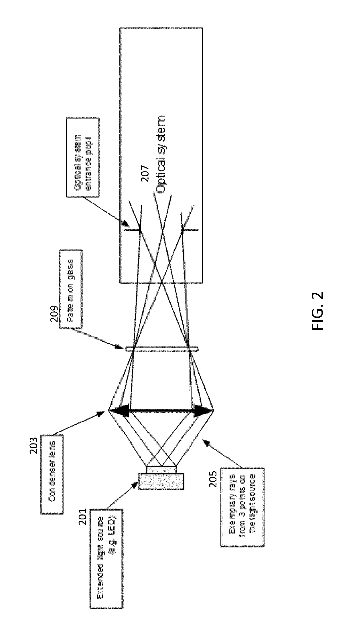
[0020]As mentioned above, described herein are handheld apparatuses for confocal (three-dimensional) scanning. These apparatuses (devices, systems, etc.) may be compact and lightweight, and may include an LED based emitter providing a reduced speckle noise. These apparatuses may also be used without requiring precise alignment (pre-alignment) as needed in other systems in which an array of light spots is used to provide confocal imaging, having a maximal alignment error that is about 0.5 micrometers or less. The confocal apparatuses described herein may be operated without the need for such precise alignment, by using a continuous pattern instead of spots array. As described herein a simple transparency may replace the spot array used in other systems. In general, these apparatuses may require substantially fewer elements than prior art devices; the apparatuses described herein may eliminate the need for one or more of: laser, color capture auxiliary illumination, and light transmitting thermal defogging means. Further, the apparatuses described herein may have a reduced lens count (e.g., requiring fewer lenses, compared to the prior art). The small projection / imaging optics system may therefore allow a very compact apparatus, and in particular may be used with a small axial actuator, such as a compact voice coil motor (VCM).
[0021]The resulting optical configuration may be simpler and less sensitive to assembly error and thermal variations than prior art apparatuses. In addition, these apparatuses may be appropriate for straightforward color implementations, without the need for a separate illumination and dichroic filter.
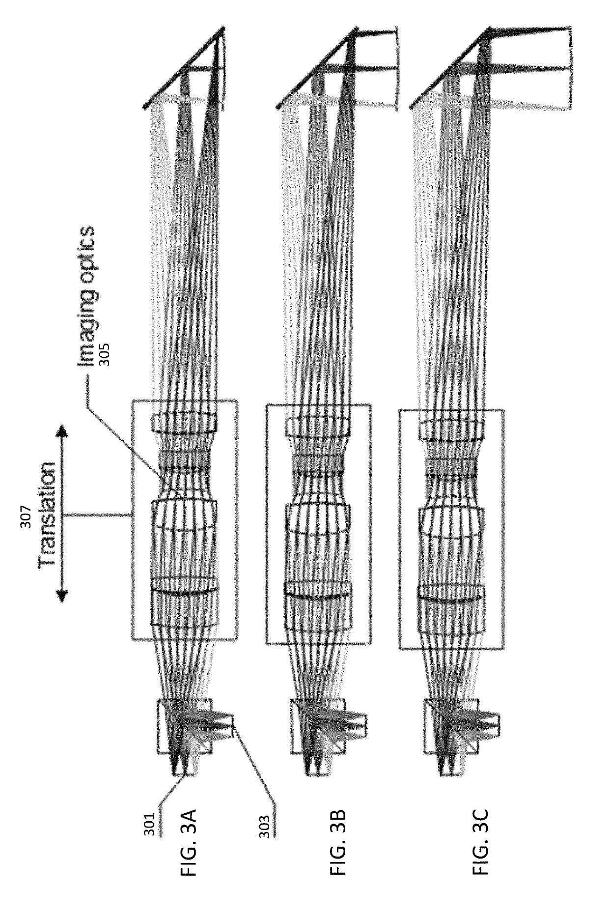
[0023]Unlike prior art apparatuses, the projection / imaging optics system may be configured to provide a deviation from telecentricity of a chief ray between the projection / imaging optics system and the fold mirror relative to a scan field size of between 3 and 10 degrees. It was previously believed (see, e.g., U.S. Pat. No. 8,878,905) that the optical system of a scanner should be substantially telecentric (e.g., having an angle of less than 3 degrees, preferably much less) in the space of the probed object (the object being scanned). In contrast, the apparatuses described herein may be non-telecentric, e.g., may deviate from telecentricity by a predetermined amount (e.g., between 3 degrees and 10 degrees, e.g., 8.5 degrees). The optical design of the apparatuses described herein may have a light source space that includes non-telecentric aperture imaging such that the entire projection / imaging optics are sufficiently compact and lightweight to be entirely translated axially (e.g., by a linear actuator / axial scanner such as VCM) to facilitate the depth scan.

