Marksman positioning device

a positioning device and marksman technology, applied in the field of firearm sights, can solve the problems of inconvenient positioning of eyes, inability to accurately position projectiles, and inability to reduce parallax, so as to facilitate repositioning, facilitate finding and viewing, and minimal disruption to the connection between marksman and firearms

Active Publication Date: 2019-10-29
ROCQUE WILLIAM
View PDF36 Cites 1 Cited by
  • Summary
  • Abstract
  • Description
  • Claims
  • Application Information

AI Technical Summary

Benefits of technology

[0010]A marksman positioning device of the present invention provides a marksman with consistent eye placement, reducing parallax error with minimal obstruction. Some embodiments, designed to be applied to an existing optical sight, may provide the additional advantage of improving the target picture produced by the sight. In other embodiments, devices of the present invention relate to the manufacture of optical sights having an alignment pattern applied to the ocular lens for the purpose of reducing parallax.
[0013]In a first aspect of the present invention, an auxiliary lens is manufactured from a relatively transparent material that is adapted to be fixed directly to an ocular lens. In a preferred embodiment, the material is pliable and fixed to the ocular lens without epoxy, glue, or other permanent adhesives. Instead, the pliable material is held to the ocular lens by forces of suction, static cling, or similar surface attractions so that the device may be easily removed from the ocular lens without damage to the sight.
[0016]An alignment pattern of the present invention is adapted for correlating with a reticle of an optical sight. The pattern is of such size and location with respect to its associated lens that, when looking through an optical sight with the device installed, the pattern appears only within a small portion of the target picture. The overall size and characteristics of the pattern allow a marksman to easily find and view the pattern and reticle simultaneously while aiming at a target and facilitates re-positioning with minimal disruption to the connection between marksman and firearm.

Problems solved by technology

Inconsistent eye positioning is especially problematic for firearms fitted with higher powered optical sights due to the phenomenon of parallax.
However, in circumstances requiring greater degrees of accuracy, such as would be needed for precise projectile placement over a long distance, a projectile may miss the expected target if the marksman's eye is incorrectly positioned.
While such devices can improve the sight picture of telescopic sights, they do little to reduce parallax.
However, viewing both the reticle and the markings around the circumference of the target picture simultaneously with a target centered in the reticle is difficult for most shooters, particularly when the target is small.
In situations involving long distance projectile placement with optical sights, parallax continues to be a challenge.

Method used


Image

  • Marksman positioning device
  • Marksman positioning device
  • Marksman positioning device

Examples


Embodiment Construction

[0025]Unless otherwise specified, the terms defined below are intended to have their broadest possible meaning within the requirements of the law. As used throughout this specification:

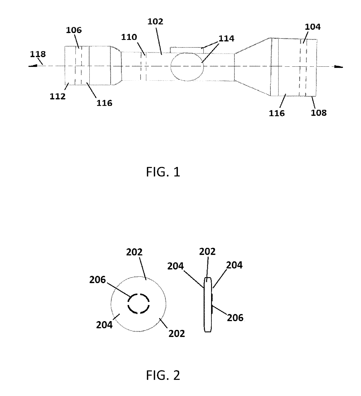
[0026]The term “aim point” refers to a point of a reticle in a target picture of an optical sight that coincides with an expected projectile trajectory at target impact. Typically, the aim point of an optical sight is overlaid upon a target for the purpose of intersecting the target with a fired projectile when shooting at the target from a distance for which the sight and a corresponding firearm were zeroed.

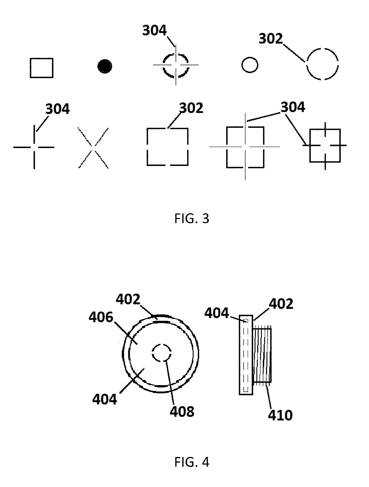
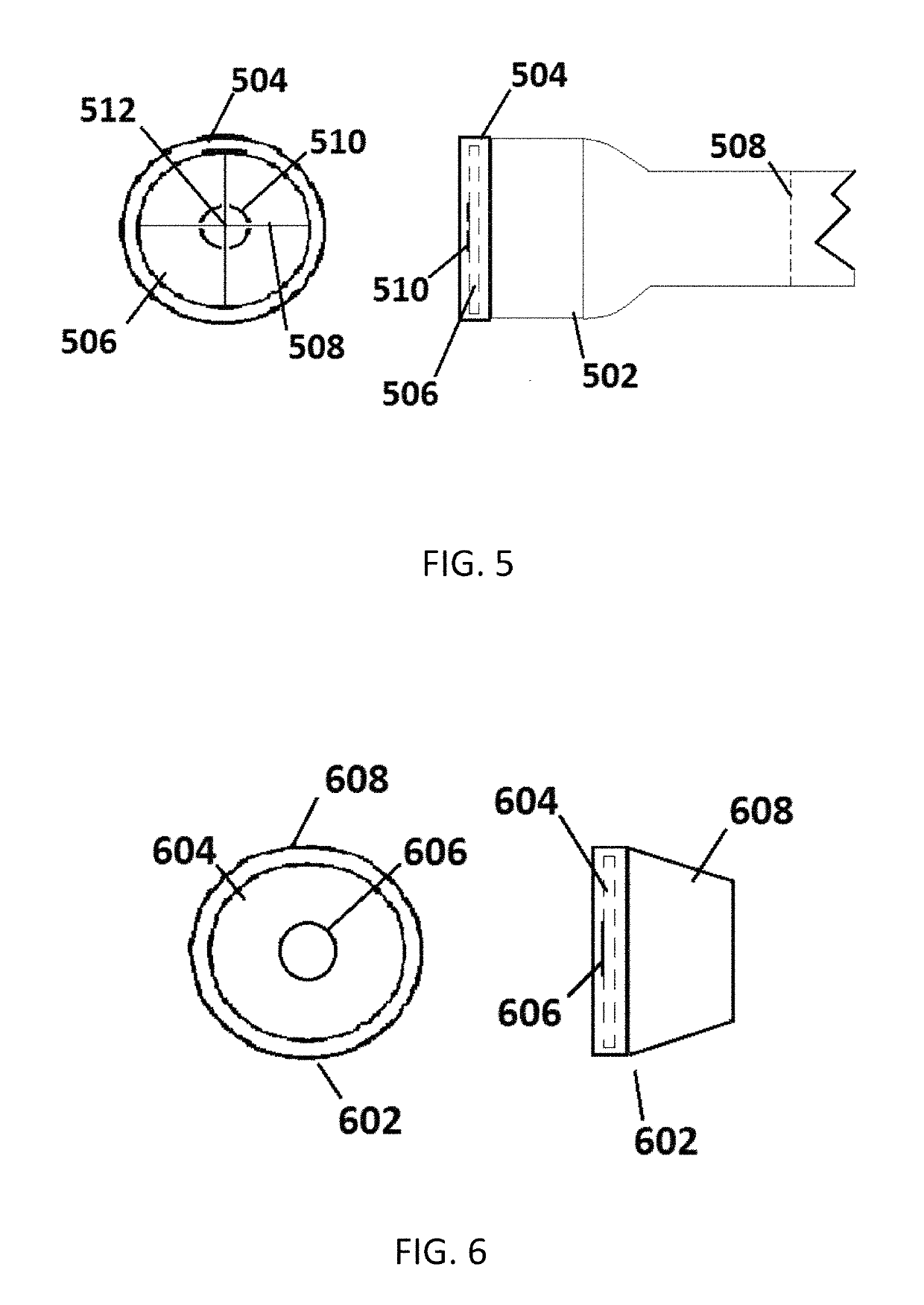
[0027]The term “alignment pattern” or “pattern” refers to a geometric indicator used in correlation with a reticle or similar aiming element of an optical sight to assess the need for adjustment of shooter position. The alignment pattern of preferred embodiments of the present invention is integral or in contact with an auxiliary or ocular lens and is small enough to be viewable only in a small ar...


PUM


Abstract

Device and related methods for improving the accuracy and precision of firearms fitted with optical sights. The device comprises a small alignment pattern for indexing against a small, central region of a target picture aimpoint or reticle. The alignment pattern is applied to an auxiliary lens fixed in position externally behind an ocular lens. The auxiliary lens is supported by a frame secured to the optical sight or the auxiliary lens is made to adhere to the outside surface of the ocular lens. Some embodiments refract or condition light to improve target pictures. Alternatively, an alignment pattern, without an auxiliary lens, is applied directly to or made integral with an ocular lens during the manufacture of an optical sight. In general, referencing the alignment pattern with the reticle, by adjusting eye placement until a desired alignment is observed, provides consistent shooter positioning and reduced parallax.

Description

CROSS REFERENCE TO RELATED APPLICATIONS[0001]This application claims the benefit of U.S. Provisional Application No. 62 / 418,685, filed Nov. 7, 2016, the disclosure of which is hereby incorporated by reference in its entirety.BACKGROUND OF THE INVENTIONField of the Invention[0002]This invention is directed to the field of firearm sights. More particularly, the invention relates to devices for consistently positioning a shooter with respect to a firearm fitted with optical sights.Description of the Related Art[0003]A consistent connection between marksman and firearm is necessary for repeatable bullet placement. Variations in hold and positioning are known to affect the performance of a firearm as well as the characteristics of the sight picture that is presented to a marksman. Inconsistent eye positioning is especially problematic for firearms fitted with higher powered optical sights due to the phenomenon of parallax.[0004]In general, optical sights incorporate an internal reticle, ...

Claims


Application Information

Patent Timeline
Patent Type & Authority Patents(United States)
IPC IPC(8): F41G1/38F41G1/42
CPCF41G1/38F41G1/42
Inventor ROCQUE, WILLIAM
Owner ROCQUE WILLIAM
Why Eureka
Try Eureka