Eye imaging with an off-axis imager

an imager and eye technology, applied in the field of virtual reality and augmented reality imaging and visualization systems, can solve the problems of difficult production of vr, ar, or mr technology that facilitates, and difficulty in acquiring other virtual or real-world imagery elements

Active Publication Date: 2019-11-05
MAGIC LEAP INC
View PDF45 Cites 40 Cited by
  • Summary
  • Abstract
  • Description
  • Claims
  • Application Information

AI Technical Summary

Problems solved by technology

As it turns out, the human visual perception system is very complex, and producing a VR, AR, or MR technology that facilitates a comfortable, natural-feeling, rich presentation of virtual image elements amongst other virtual or real-world imagery elements is challenging.

Method used


Image

  • Eye imaging with an off-axis imager
  • Eye imaging with an off-axis imager
  • Eye imaging with an off-axis imager

Examples


Embodiment Construction

Overview

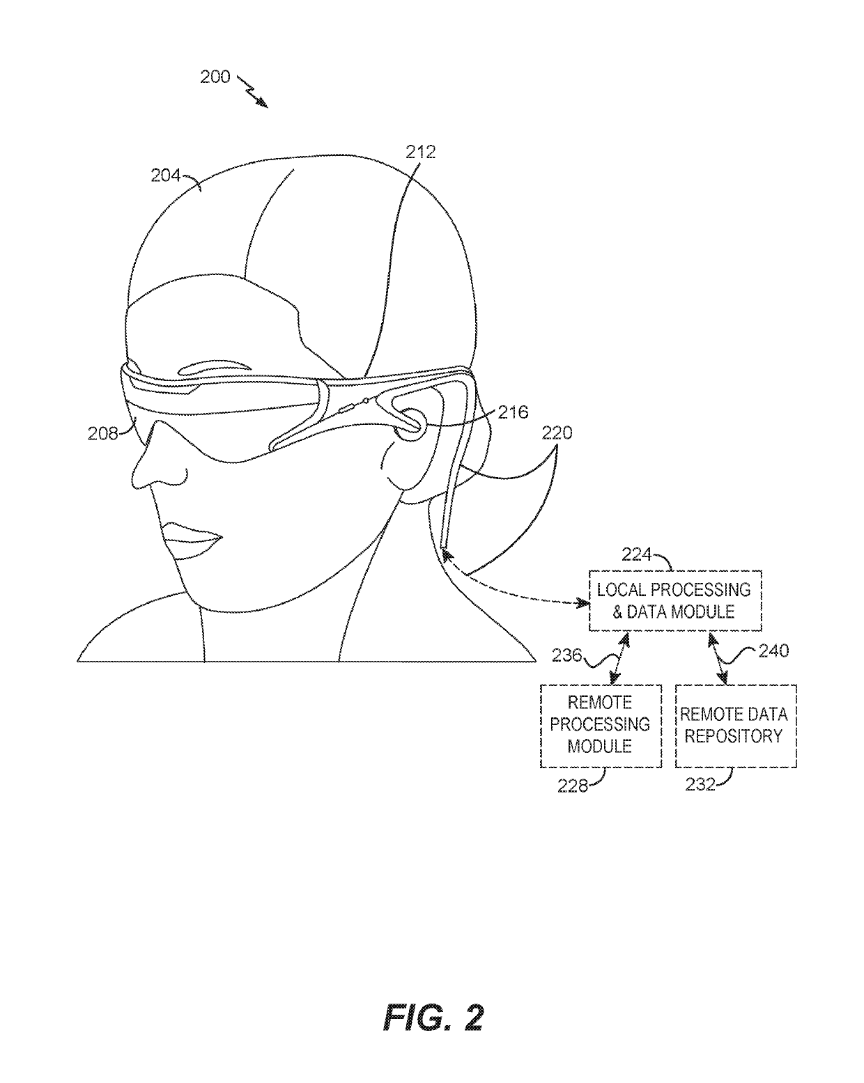
[0017]The eyes of a wearer of a head mounted display (HMD) can be imaged using a reflective off-axis Diffractive Optical Element (DOE). In some implementations, the DOE may be a Holographic Optical Element (HOE), an off-axis holographic mirror (OAHM), or an off-axis volumetric diffractive optical element (OAVDOE). The resulting images can be used to track an eye or eyes, image the retina, reconstruct the eye shape in three dimensions, extract biometric information from the eye (e.g., iris identification), etc.

[0018]A head mounted display (HMD) might use information about the state of the eyes of the wearer for a variety of purposes. For example, this information can be used for estimating the gaze direction of the wearer or for biometric identification. However, imaging the eyes of a wearer of a HMD can be challenging. The distance between the HMD and the wearer's eyes is short. Furthermore, gaze tracking requires a larger field of view, while biometric identification requir...


PUM


Abstract

Examples of an imaging system for use with a head mounted display (HMD) are disclosed. The imaging system can include a forward-facing imaging camera and a surface of a display of the HMD can include an off-axis diffractive optical element (DOE) or hot mirror configured to reflect light to the imaging camera. The DOE or hot mirror can be segmented. The imaging system can be used for eye tracking, biometric identification, multiscopic reconstruction of the three-dimensional shape of the eye, etc.

Description

CROSS-REFERENCE TO RELATED APPLICATIONS[0001]This application claims the benefit of priority under 35 U.S.C. § 119(e) to U.S. Provisional Application No. 62 / 222,671, filed on Sep. 23, 2015, entitled “EYE IMAGING WITH AN OFF-AXIS IMAGER,” which is hereby incorporated by reference herein in its entirety.BACKGROUND[0002]Field[0003]The present disclosure relates to virtual reality and augmented reality imaging and visualization systems and in particular to imaging systems for acquiring images of an eye.[0004]Description of the Related Art[0005]Modern computing and display technologies have facilitated the development of systems for so called “virtual reality” or “augmented reality” experiences, wherein digitally reproduced images or portions thereof are presented to a user in a manner wherein they seem to be, or may be perceived as, real. A virtual reality, or “VR”, scenario typically involves presentation of digital or virtual image information without transparency to other actual real...

Claims


Application Information

Patent Timeline
Patent Type & Authority Patents(United States)
IPC IPC(8): G02B27/01A61B3/113G02C11/00A61B3/10A61B3/12A61B3/14G02B27/00A61B5/16A61B5/11A61B5/00A61B5/117
CPCG02B27/0172A61B3/113A61B5/1122A61B3/12A61B5/742G02B27/0093A61B3/10A61B5/163A61B3/14G02B2027/0138G02B2027/0178A61B5/117G02B2027/014
Inventor KLUG, MICHAEL ANTHONYKAEHLER, ADRIAN
Owner MAGIC LEAP INC
Why Eureka
Try Eureka