
Flow-controlling pacifier weaning apparatus

a weaning apparatus and flow control technology, applied in the field of pacifiers, can solve problems such as considerable stress, and achieve the effect of minimizing rejection and maximizing apparatus adoption

Active Publication Date: 2019-11-12
MEDPORT
View PDF9 Cites 0 Cited by
  • Summary
  • Abstract
  • Description
  • Claims
  • Application Information

AI Technical Summary

Benefits of technology

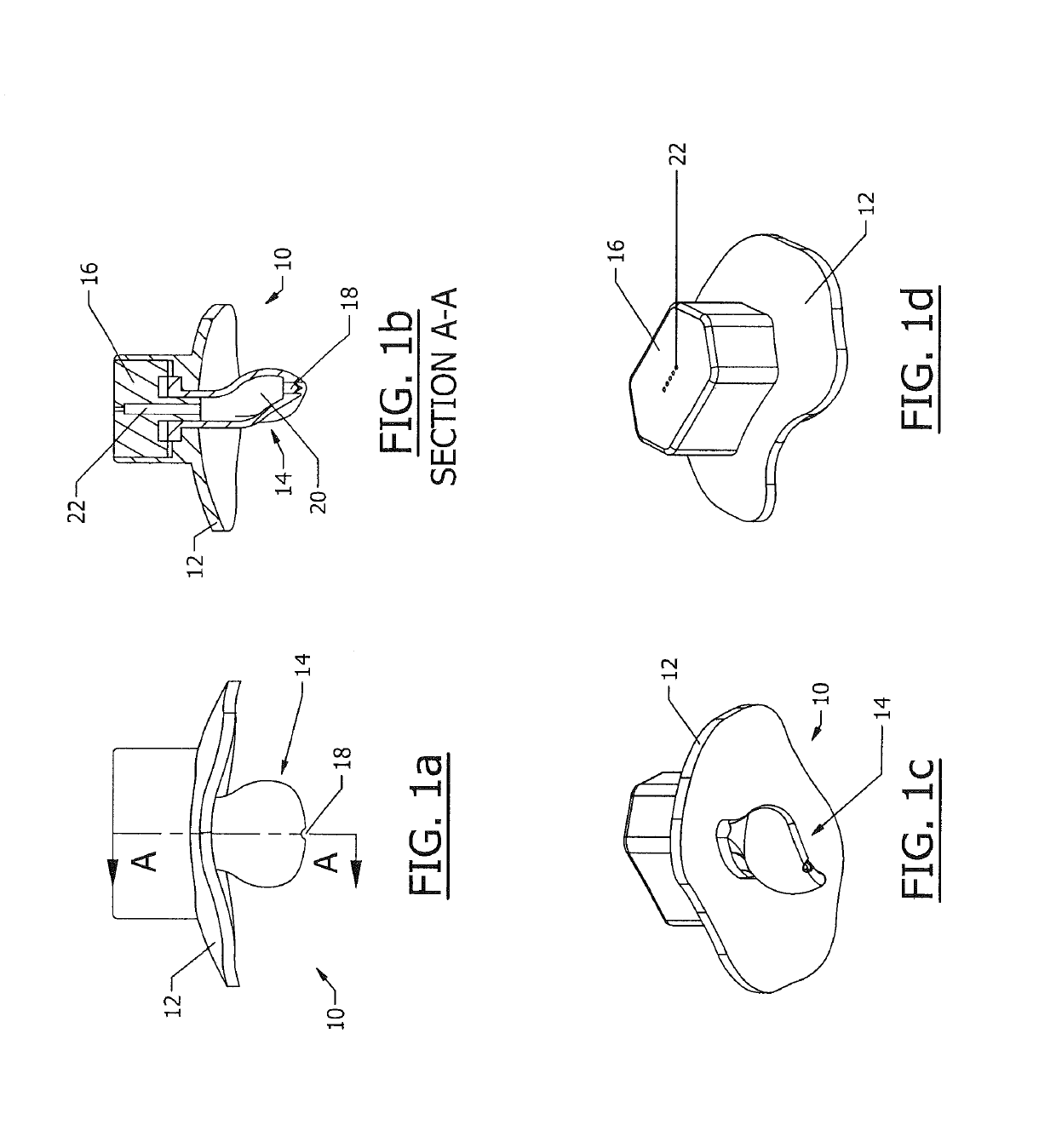
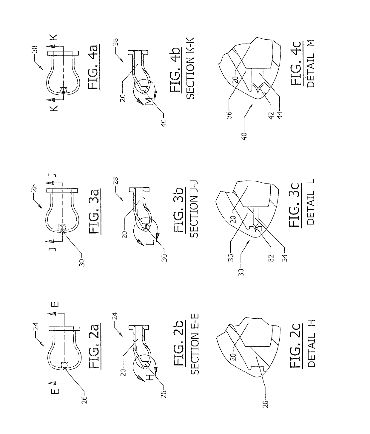
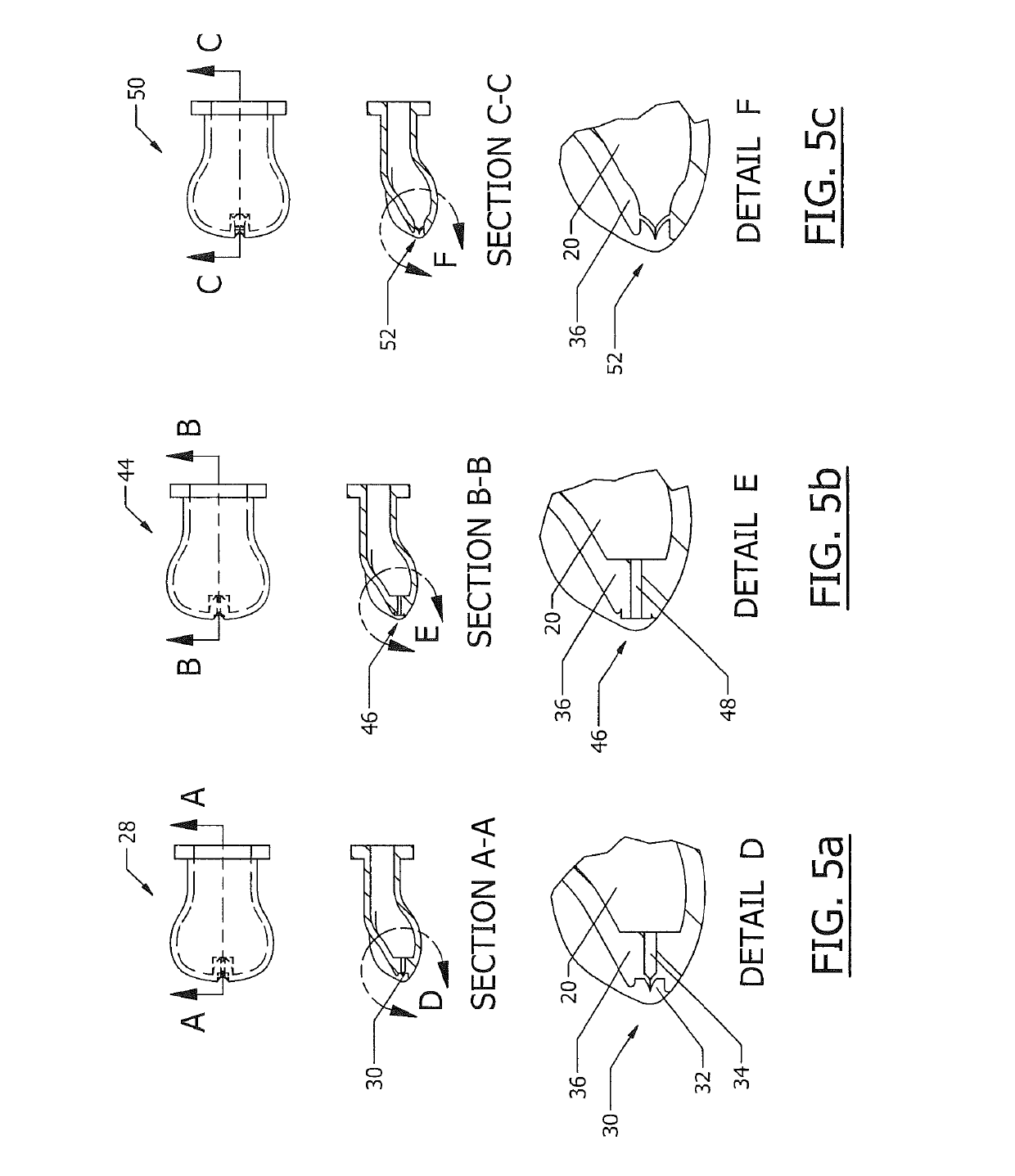
[0012]Example implementations of the present disclosure provide an improved pacifier apparatus and method that takes into account, simultaneously, the three aforementioned principles that drive non-nutritive sucking. The apparatus is designed for discouraging its use, in a gentle manner which does not result in abrupt rejection and undesirable frustration by a user such as a child. The apparatus is designed to allow an administrator to control, simultaneously, both the ability of the child to expand a hollow chamber of a nipple and the partial vacuum pressure attained by the child during sucking activity, by controlling when and how air flows out of the nipple and into the child's mouth. By incorporating a series of airflow-control components, comprised of valves, passageways, or combinations thereof, the administrator can control both the peak and rhythm of the sinusoid sucking cycle.
[0023]According to other aspects of example implementations of the present disclosure, airflow-control components for pacifier weaning apparatuses are provided. Example implementations of the present disclosure therefore provide improved apparatuses for controlling the flow of air to break the partial vacuum, in a manner which maximizes apparatus adoption and minimizes rejection. As indicated above and explained below, example implementations of the present disclosure may provide one or more advantages over existing techniques.

Problems solved by technology

This rejection tends to be sudden and can cause considerable stress, comparable to removing the pacifier directly.

Method used


Image

  • Flow-controlling pacifier weaning apparatus
  • Flow-controlling pacifier weaning apparatus
  • Flow-controlling pacifier weaning apparatus

Examples


Embodiment Construction

[0038]The present disclosure now will be described more fully hereinafter with reference to the accompanying drawings, in which preferred implementations of the disclosure are shown. This disclosure may, however, be embodied in many different forms and should not be construed as limited to the implementations set forth herein; rather, these implementations are provided so that this disclosure will be thorough and complete, and will fully convey the scope of the disclosure to those skilled in the art. For example, references may be made herein to directions and orientations including vertical, horizontal, diagonal, right and left, front and back; it should be understood, however, that any direction and orientation references are simply examples and that any particular direction or orientation may depend on the particular object, and / or the orientation of the particular object, with which the direction or orientation reference is made. Like numbers refer to like elements throughout.

[0...


PUM


Abstract

A pacifier weaning apparatus is provided that includes a shell or shell assembly providing a housing, and a nipple configured to protrude from the housing. The nipple includes a first end adapted to be held by the housing, and an opposing, sucking end adapted for insertion into a user's mouth. The nipple also defines a first chamber and an expandable, second chamber that are both open at the first end and extend in a direction from the first end to the sucking end, and the first chamber being open and the second chamber being closed at the sucking end. And the pacifier weaning apparatus includes an airflow-control component configured to regulate either or both a break pressure at or above which airflow through the first chamber is permitted, or a rate of airflow through the first chamber.

Description

CROSS-REFERENCE TO RELATED APPLICATION(S)[0001]The present application is a national-stage entry of PCT Patent Application No. PCT / US2014 / 058014, filed on Sep. 29, 2014, which claims priority to U.S. Provisional Patent Application No. 61 / 885,277, entitled: Flow-Controlling Pacifier Weaning Apparatus, filed on Oct. 1, 2013, the content of which is incorporated herein by reference in its entirety.FIELD OF THE INVENTION[0002]The present disclosure generally relates to pacifiers, and more particularly, to a flow-controlling pacifier weaning apparatus for discouraging pacifier use by a user such as a child.BACKGROUND OF THE INVENTION[0003]From birth, all infants have a natural instinct to suck; this is in order to receive nutrition through breast feeding, a behavior which is not only completely normal, but necessary for survival. From the very first time they engage in breast feeding, infants learn that sucking can not only provide valuable nourishment, but also a great deal of pleasure,...

Claims


Application Information

Patent Timeline
Patent Type & Authority Patents(United States)
IPC IPC(8): A61J11/00A61J17/00A61J7/00
CPCA61J17/006A61J11/002A61J17/001A61J7/0053A61J17/10A61J17/105
Inventor ZILBER, DAVID
Owner MEDPORT
Learn More