
Wireless monitoring system

a monitoring system and wireless technology, applied in the field of wireless monitoring systems, can solve the problems of complicated protocol stack of such systems, and achieve the effects of saving power, saving energy, and prolonging battery li

Active Publication Date: 2019-11-12
SENSO2ME NV
View PDF8 Cites 4 Cited by
  • Summary
  • Abstract
  • Description
  • Claims
  • Application Information

AI Technical Summary

Benefits of technology

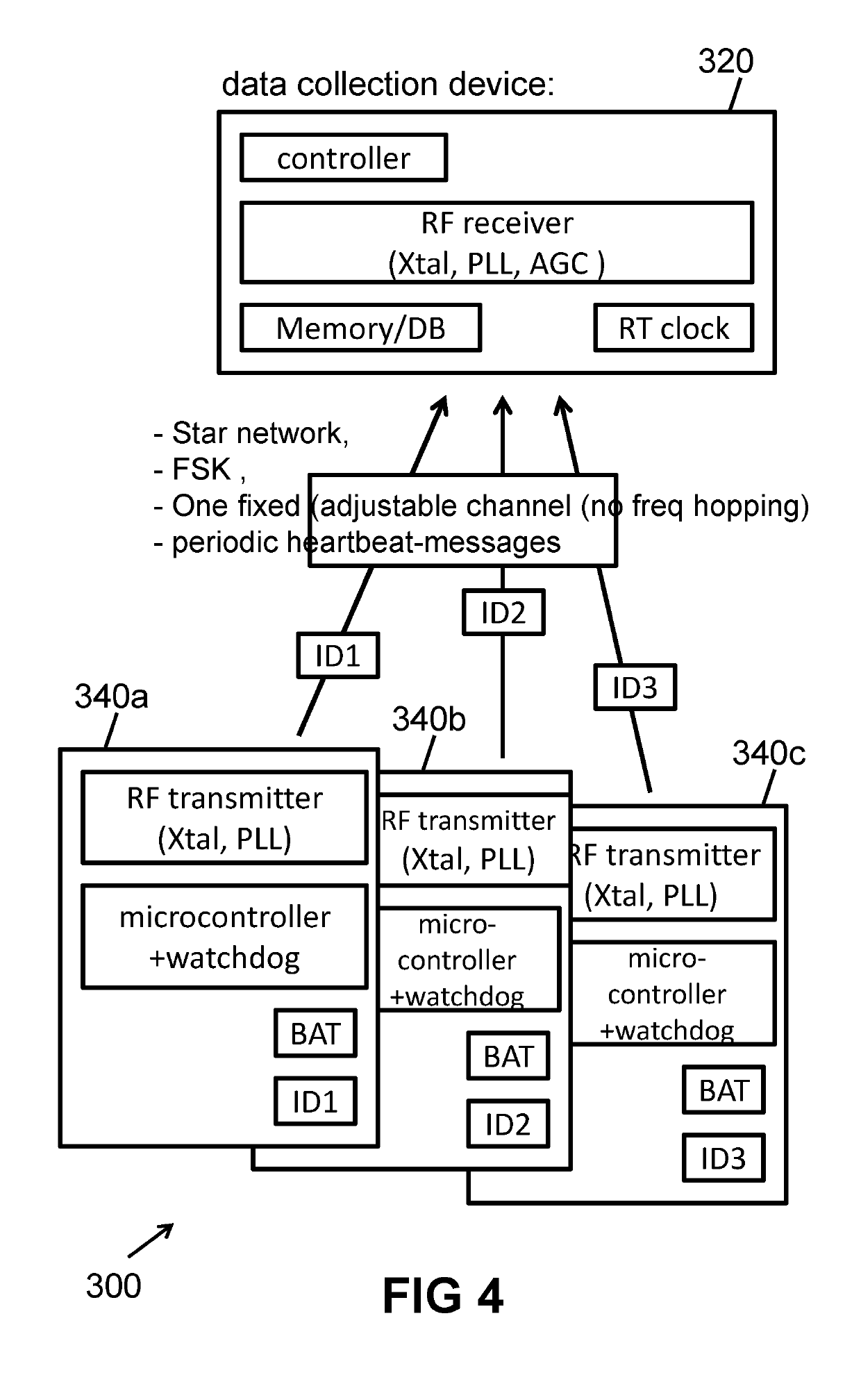
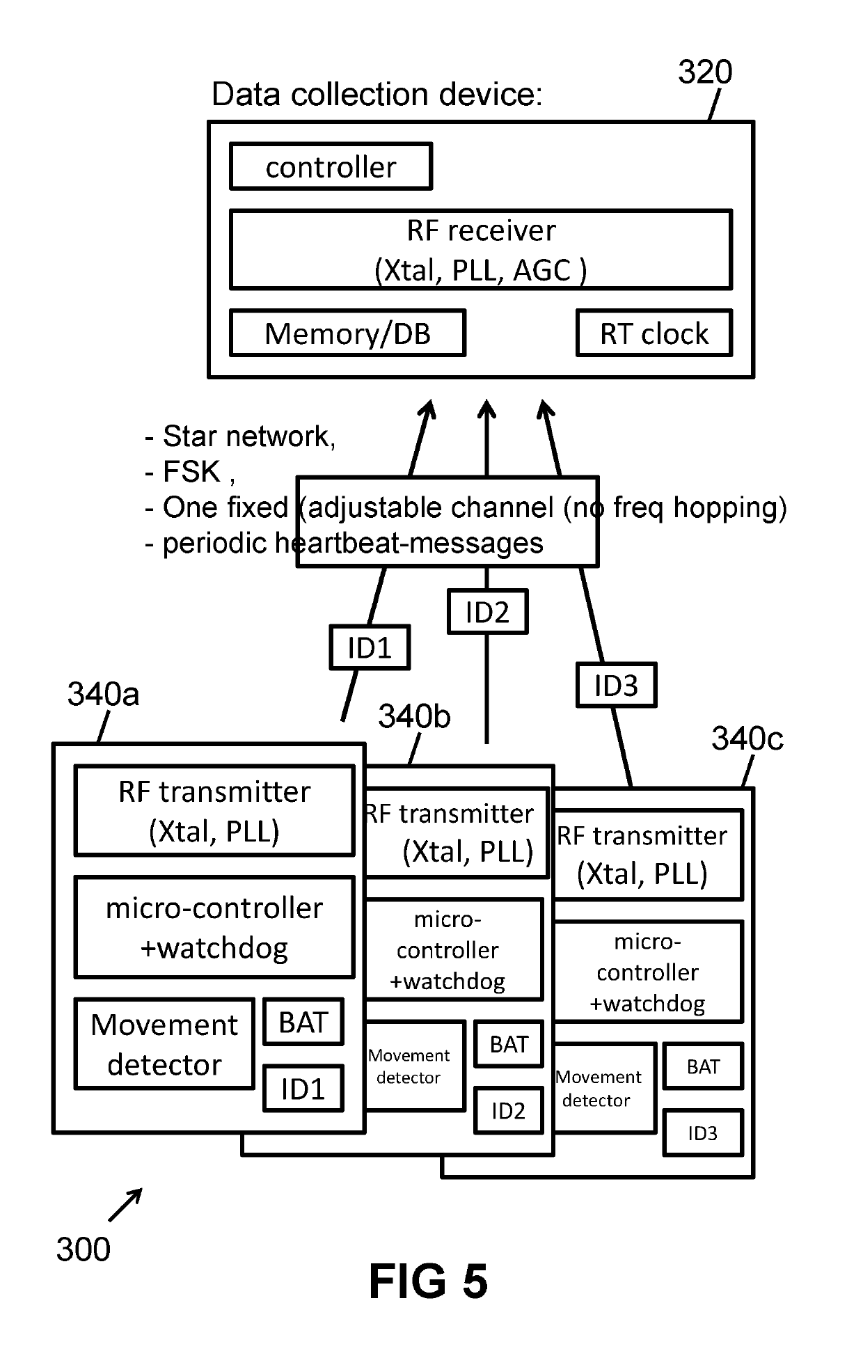
[0032]It is an advantage of the present invention that it does not work according to the ZigBee protocol or LoRa (Long Range) protocol, but according to its own protocol, in which the signalling devices do not have to check whether a signal is sent to the appropriate signalling device after each message. In other words, this means that the receiving portion of such a transceiver is activated less often than the transmitter, whereby power is saved. Preferably, only up to 1 / 10 or 1 / 20 or 1 / 50 of the messages that are sent are messages that are sent from the data collection device to the signalling devices.
[0033]In an embodiment, each signalling device is adapted to only send messages via its RF circuit, and to not receive any messages via its RF circuit.
[0034]It is an advantage of embodiments of the present invention that the wireless signalling devices are adapted to only send data to the data collection device, but not to receive it, and that preferably the data collection device is also adapted to only receive data from the wireless signalling devices, but not to send it, via the respective RF circuits. This allows the RF circuit of the signalling device to only act as ‘transmitter’ and that the RF circuit of the data collection device only acts as ‘receiver’ and that therefore no transceivers are required. This has the advantage that the wireless signalling devices consume no power to receive messages (by listening on the channel), and that the wireless signalling devices do not need an AGC (automatic gain control) circuit (just a PLL), and that the microcontroller of the wireless signalling devices need not be adapted to sync with an external clock signal, but can operate only on the basis of an internal clock.
[0035]It is an advantage that at least a portion of the RF circuit is only supplied with power when data actually needs to be sent, whereby energy is saved, and the battery will last longer.
[0036]In an embodiment, the data collection device is further provided with means to determine a signal strength of the signals sent by the signalling devices.
[0037]The signal strength can, for example, be determined by reading out the value of the gain of the AGC circuit. This value can provide useful information, depending on the application.

Problems solved by technology

However, the protocol stack of such systems can be very complicated.

Method used


Image

  • Wireless monitoring system
  • Wireless monitoring system
  • Wireless monitoring system

Examples


Embodiment Construction

[0206]Although the present invention will hereinafter be described with respect to particular embodiments and with reference to certain drawings, the invention is not limited thereto but only by the claims.

[0207]Reference throughout this specification to ‘one embodiment’ or ‘an embodiment’ means that a particular feature, structure or characteristic described in connection with the embodiment is included in at least one embodiment of the present invention. Thus, instances of the phrases ‘in one embodiment’ or ‘in an embodiment’ in various places throughout this specification may, but do not necessarily, all refer to the same embodiment. Furthermore, the particular features, structures or characteristics may be combined in any suitable manner, as would be apparent to one of ordinary skill in the art from this disclosure, in one or more embodiments.

[0208]Similarly it should be appreciated that in the description of illustrative embodiments of the invention, various features of the inv...


PUM


Abstract

A wireless monitoring system for monitoring at least one person in a building. The wireless monitoring system comprises a data collection device and a plurality of wireless signalling devices working in a star network topology, the data collection device being adapted to wirelessly receive data transmitted from each of the plurality of wireless signalling devices. The signalling devices and the data collection device being adapted to send and receive FSK modulated signals in a predetermined single channel and the signalling devices being adapted to send data packets such as a heartbeat message to the data collection device.

Description

FIELD OF THE INVENTION[0001]The present invention relates generally to the field of wireless monitoring systems, in particular for the monitoring of one or more persons in one or more buildings. More specifically, the present invention relates to a mobility monitoring system, and a wireless signalling device and a data collection device that can be used in such systems.BACKGROUND OF THE INVENTION[0002]Wireless network systems, for example, wireless communication systems or wireless sensor systems, where a plurality of transmission units send data to one or more receiver units by means of wireless signals, are known in the prior art.[0003]They can be classified in various ways, including, based on the nature of the wireless signals (optical, acoustic, electromagnetic, etc.). For the present invention only RF signals are relevant. There are many different modulation techniques, each with their own specific advantages and disadvantages. For example, amplitude modulation (AM) is highly ...

Claims


Application Information

Patent Timeline
Patent Type & Authority Patents(United States)
IPC IPC(8): G08B1/08H04W52/02H04W8/00G08B21/22H04L27/10H04L12/44
CPCH04W8/005H04W52/0225H04W52/0219H04W52/0254H04W52/0216G08B21/22Y02D70/166H04L12/44Y02D70/00Y02D70/22Y02D70/1222Y02D70/1242Y02D70/162Y02D70/142H04L27/10Y02D70/1224Y02D70/144Y02D30/70
Inventor SCHUELER, JOHANNES BERNARDUSPHILIPS, WILFRIED RICHARD HORTENSEKLEIHORST, RICHARDVAN BUYTEN, ALAIN MYRIAM ROBERTDEBOIS, STEFAN ALBERT DENISE
Owner SENSO2ME NV
Learn More