Keyswitch structure

a keyswitch and structure technology, applied in the direction of electric switches, contact mechanisms, electrical apparatus, etc., can solve the problems of affecting the stability of movement of the two supports, affecting the stability of the engagement of the two supports and the stability of movement, and the difficulty of assembling the pivotally connecting structures of the two supports. , to achieve the effect of reducing axial deformation, and enhancing the stability of the engagemen

Active Publication Date: 2019-11-12
DARFON ELECTRONICS CORP
View PDF13 Cites 3 Cited by
  • Summary
  • Abstract
  • Description
  • Claims
  • Application Information

AI Technical Summary

Benefits of technology

[0003]In view of the problem in the prior art, the present invention provides a keyswitch structure, of which two supports have pivotally connecting structures that interlock with each other. The pivotally connecting structures further include corresponding interference structures, for reducing axial deformation and enhancing the stability of the engagement of the two supports.
[0004]A keyswitch structure according to the invention includes a keycap, a base plate, a first support, and a second support. The base plate is disposed under the keycap. The first support is connected to and between the keycap and the base plate and includes a first main body and a first pivotal connection portion disposed on the first main body. The first pivotal connection portion includes a first shaft socket, a first shaft portion, and a protruding interference portion. The first shaft socket, the first shaft portion, and the protruding interference portion are adjacently arranged along a rotation axis. The second support is connected to and between the keycap and the base plate and includes a second main body and a second pivotal connection portion disposed on the second main body. The second pivotal connection portion includes a recess interference portion, a second shaft socket, and a second shaft portion. The second shaft portion, the second shaft socket, and the recess interference portion are adjacently arranged along the rotation axis. The recess interference portion has a relief space and a block beside the relief space. The first pivotal connection portion and the second pivotal connection portion are pivotally connected by the first shaft portion rotatably disposed in the second shaft socket and the second shaft portion rotatably disposed in the first shaft socket, so that the keycap is capable of moving up and down relative to the base plate through the first support and the second support. Therein, the protruding interference portion is located in the relief space. The block obstructs the protruding interference portion moving out of the relief space. Thereby, the pivotal connection of the first pivotal connection portion and the second pivotal connection portion is achieved mainly by the first shaft portion, the first shaft socket, the second shaft socket, and the second shaft portion. The interaction of the protruding interference portion and the recess interference portion can enhance the stability of the engagement of the first pivotal connection portion and the second pivotal connection portion.
[0005]Compared to the prior art, in the keyswitch structure according to the invention, the pivotal connection of the first support and the second support is achieved by the first shaft portion, the first shaft socket, the second shaft socket, and the second shaft portion engaging with each other, which can reduce or avoid the axial deformation in the prior art. Furthermore, the interaction of the protruding interference portion and the recess interference portion can make the engagement of the first pivotal connection portion and the second pivotal connection portion stable, which can avoid the fact in the prior art that the pivotally connecting structures interlocking with each other tend to be disengaged from each other. In other words, the keyswitch structure according to the invention can reduce axial deformation and maintain the stable pivotal connection of the first support and the second support.

Problems solved by technology

However, when the keyswitch structure or the lift mechanism is reduced in size, some structural deformation probably remains in the shafts, the shaft holes, or the main bodies of the supports after the two supports are pivotally connected, which affects the stability of movement of the two supports.
This structural feature also makes the two engaged supports tend to be disengaged from each other, which affects the stability of the engagement of the two supports and the stability of movement thereof as well.
Though the degree of the structural interference of the corresponding hole portion and shaft portion in assembling can be raised to enhance the stability of the engagement of the two supports, it makes the assembling of the pivotally connecting structures of the two supports difficult and makes structural deformation remain in the pivotally connecting structures, which also affects the stability of movement of the two supports.

Method used


Image

  • Keyswitch structure
  • Keyswitch structure
  • Keyswitch structure

Examples


Embodiment Construction

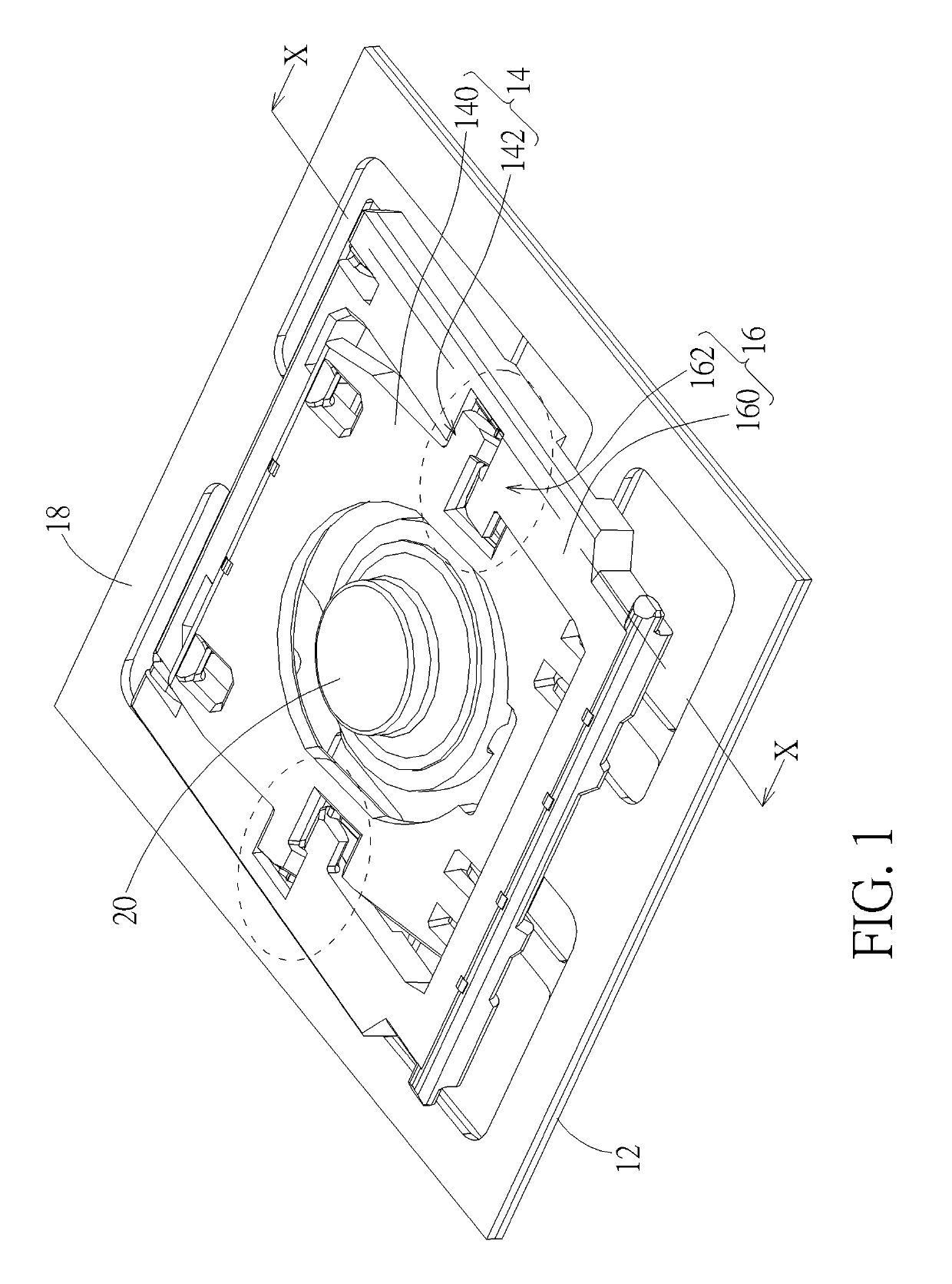
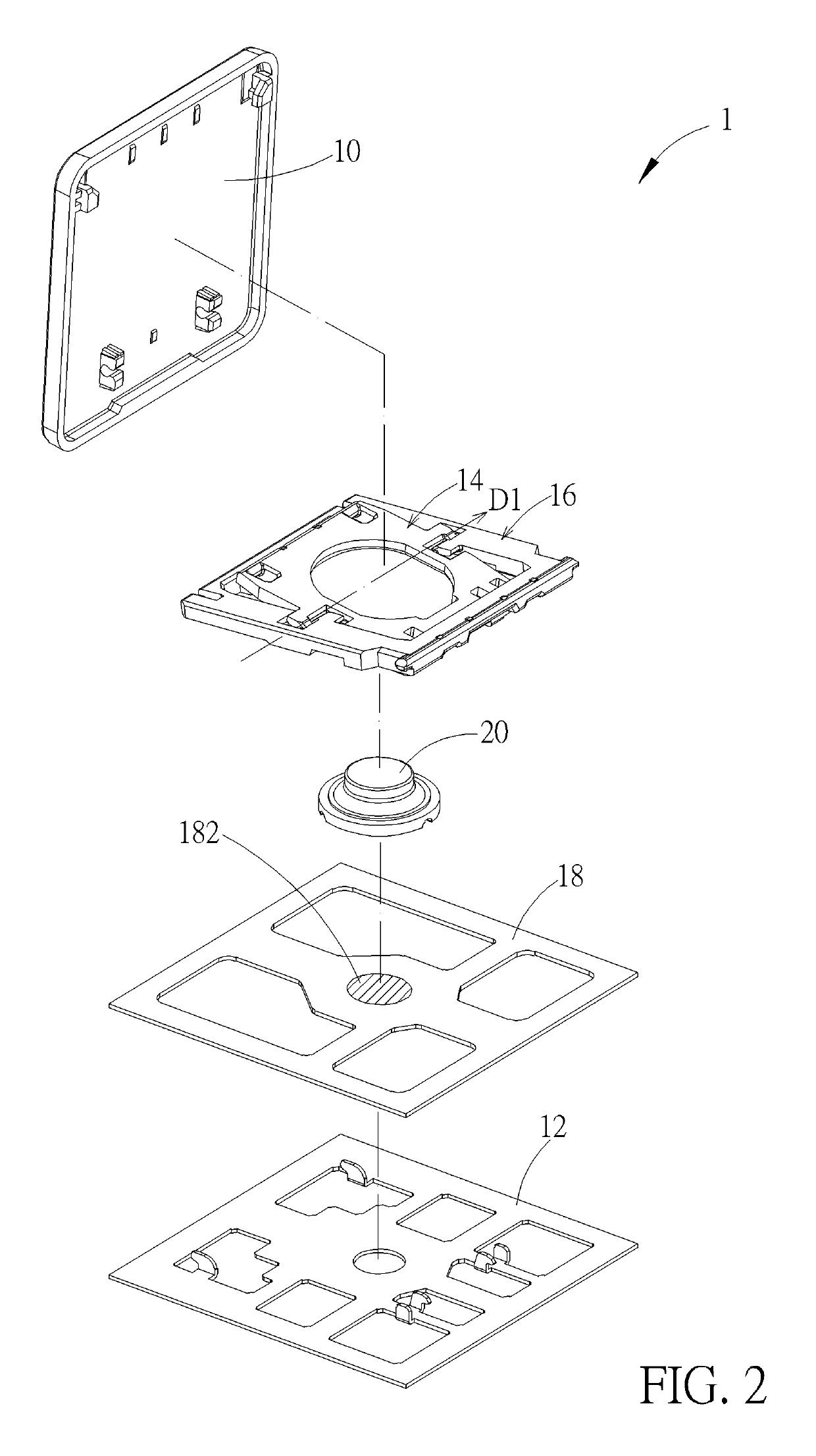
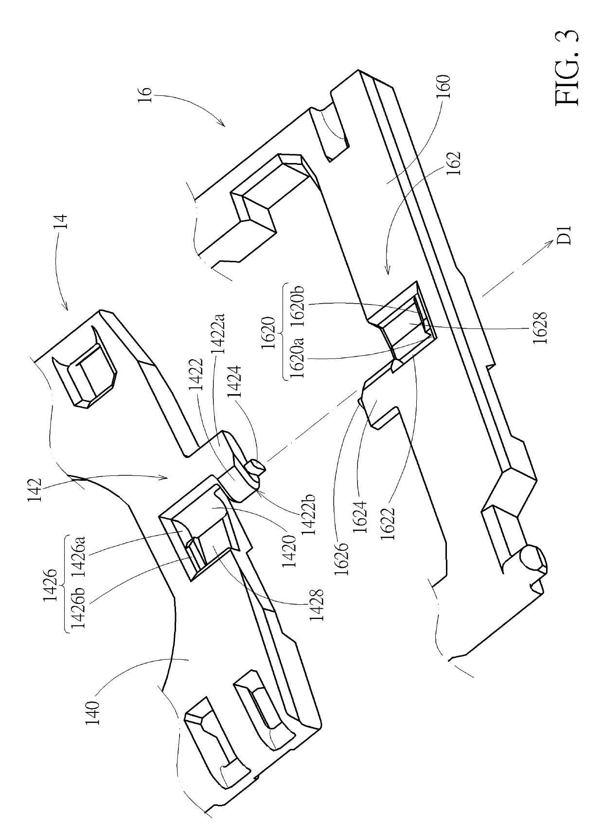
[0017]Please refer to FIG. 1 to FIG. 4. A keyswitch structure 1 of an embodiment according to the invention includes a keycap 10, a base plate 12, a first support 14, a second support 16, a membrane circuit board 18, and an elastic dome 20. The base plate 12 is disposed under the keycap 10. The first support 14 is connected to and between the keycap 10 and the base plate 12. The first support 14 includes a first main body 140 and a first pivotal connection portion 142 disposed on the first main body 140. The first pivotal connection portion 142 includes a first shaft socket 1420, a first shaft portion 1422, and a first protruding interference portion 1424. The second support 16 is connected to and between the keycap 10 and the base plate 12. The second support 16 includes a second main body 160 and a second pivotal connection portion 162 disposed on the second main body 160. The second pivotal connection portion 162 includes a second recess interference portion 1620, a second shaft ...


PUM


Abstract

A keyswitch structure includes a keycap, a base plate, a first support, and a second support. The first support and the second support are pivotally connected with each other and are connected to and between the keycap and the base plate. The first support includes a shaft socket, a shaft portion, and a protruding interference portion which are adjacently arranged. Correspondingly, the second support includes a shaft portion, a shaft socket, and a recess interference portion which are adjacently arranged. The recess interference portion has a relief space and a block beside the relief space. The first support and the second support are pivotally connected by engaging the shaft sockets with the corresponding shaft portions; therein, the protruding interference portion is located in the relief space, and the block obstructs the protruding interference portion moving out of the relief space.

Description

BACKGROUND OF THE INVENTION1. Field of the Invention[0001]The present invention relates to a keyswitch structure, and more particularly to a keyswitch structure having supports pivotally connecting with each other.2. Description of the Prior Art[0002]Conventional keyboards include a base plate and a plurality of keycaps disposed above the base plate. Each keycap is connected to the base plate through a lift mechanism in principle so as to move up and down relative to the base plate. A common lift mechanism, e.g. scissors support, is realized by two supports pivotally connecting with each other, e.g. an inner ring support and an outer ring support. The inner ring support is pivotally connected to the inner side of the outer ring support, in general through a hole / shaft fit. For example, the inner support has a shaft protruding outward along a rotation axis at two sides thereof. The outer support has a shaft hole at corresponding inner sides thereof. Then the pivotal connection of the...

Claims


Application Information

Patent Timeline
Patent Type & Authority Patents(United States)
IPC IPC(8): H01H3/12H01H13/7065H01H13/12
CPCH01H13/12H01H3/122H01H13/7065H01H3/125
Inventor CHANG, LI-TEYEN, CHIH-CHUNG
Owner DARFON ELECTRONICS CORP
Why Eureka
Try Eureka