Drill pipe with tool joints

a tool joint and pipe technology, applied in the direction of drilling pipes, hose connections, mechanical equipment, etc., can solve the problems of increased metal consumption, uneven outwear of flash weld tool joints, and increased flexural rigidity, so as to increase the durability of tool joints

Inactive Publication Date: 2010-03-30
TEMERSO ENG
View PDF12 Cites 2 Cited by
  • Summary
  • Abstract
  • Description
  • Claims
  • Application Information

AI Technical Summary

Benefits of technology

[0009]The result that is achieved through implementation of the proposed technology consists in the increased durability of tool joints integrated in drill pipes.
[0012]The phosphate coating increases the corrosion stability of a joint, especially on segments with no zinc coating.
[0013]The fact that segments 15 to 25 mm from the welding spot are only coated with phosphate results in greater durability of a drill pipe due to the enhanced reliability of the welded connection between the joint and the pipe body.

Problems solved by technology

Certain pipes with flash weld tool joints do not outwear evenly.
Due to the margin, metal consumption is increased, flexural rigidity becomes greater, and the dimensions of tool joints, larger.
Revamping of pipes is only possible at pipe yards thus the overall maintenance expenses must include charges for transportation pipes to the yard and back.
Such a coating enhances corrosion stability and increases resistance to wear of thread connections but the coating process is very complex, which is a shortcoming.
However the coating wears out after first making-up / breakout cycles, with maximum of ten cycles, followed by wearing out of metal thread.
Therefore, the coating currently in use does not enhance the endurance capability of tool joints.

Method used


Image

  • Drill pipe with tool joints
  • Drill pipe with tool joints

Examples


Embodiment Construction

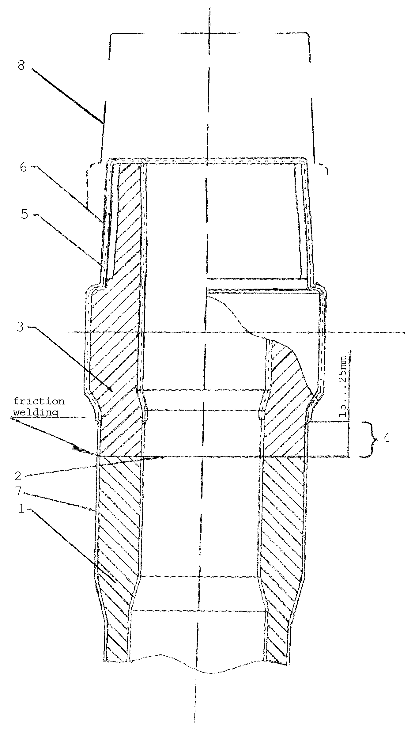
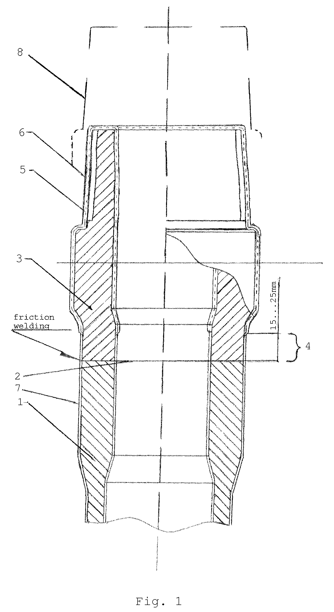
[0017]A drill pipe consists of the pipe body 1 connected by permanent connection at both ends 2 (welded connection) with connecting joints (tool joints) 3, having either external or internal tapered thread. As an example, FIG. 1 contains Joint 3 with an external thread (pipe nipple). The other pipe end with a joint with an internal thread is not shown in the FIGURE. The relevant specifications of this pipe end are completely analogous.

[0018]The whole surface of joints except Segment 4 of 15 to 25 mm long from the welding spot, is treated with Coating 5 and applied by means of thermo-diffusion zincing. The thickness δ of Coating 5 measured in μ (micrometers) is 0.09 to 0.13 K, where K is the conicity of the thread. This correlation is experimentally established for conicity values ranging from ⅙ to ¼, i.e. for most often used values of tool-joint threads.

[0019]There is Phosphate Layer 6 over Coating 5. During fabrication of tool joints it is applied on both segment 4 and the frontal ...


PUM


Abstract

The engineering problem of the claimed invention is to enhance wear-resistance of drill pipe tool joints. The proposed drill pipe consists of a body with upset ends and tool joints connected by means of friction welding, having tapered thread and a double coating, the first layer being applied by means of thermo-diffusion zincing and the second one, by means phosphate treatment. Enhancement of tool joint life, as compared to the tool joints with phosphate coating only, allows no overdimension to be stipulated for future repair purposes, which saves up to several kilos of metal per tool joint, decreasing the drill string weight by several tons. With a view to increasing the joints' durability and reliability of welding seams the thickness δ of the first coating layer as function of thread conicity K is adjusted according to the following formula: δ=0.09 . . . 0.13 K. The segment at 15 to 25 mm from the welding spot on joints is coated with phosphate only.

Description

RELATED APPLICATIONS[0001]This application is a Continuation of PCT application serial number PCT / IB / 2008 / 001923 filed on Jul. 14, 2008, which in turn claims priority to Russian Patent Application No. RU 2007127484 filed on Jul. 19, 2007.FIELD OF THE INVENTION[0002]The invention pertains to drilling equipment, namely drill pipes that are used to drill exploration, oil and gas wells.BACKGROUND OF THE INVENTION[0003]A drill pipe consists of a pipe itself—a rather long component that is almost untreated mechanically, and of interlocking devices with the threaded connections (further referred to as joints or tool joints). The latter are located at both pipe's ends forming either integral joints or permanent connections. This very device will be further denoted by the term “drill pipe”. The term “pipe” will denote a semifinished drill pipe without tool joints.[0004]Tool joints connect pipes into a drill string and represent elements with external tapered thread (referred to as the pipe n...

Claims


Application Information

Patent Timeline
Patent Type & Authority Patents(United States)
IPC IPC(8): F16L11/12
CPCE21B17/042E21B17/1085F16L57/00
Inventor GETMAN, ALEKSANDR VLADIMIROVICHSTEPANOVA, SVETLANA SEMYONOVNATRIFONOV, YURIY ALEKSEEVICH
Owner TEMERSO ENG
Why Eureka
Try Eureka