
Bone fusion device

a bone fusion and bone technology, applied in the field of bone fusion devices, can solve the problems of bringing obvious bone-conducted stimulation, affecting the efficiency of bone growth, and the stability of the device, so as to improve the shortcomings of the prior, and strengthen the stability of engagemen

Active Publication Date: 2017-09-19
OSSAWARE BIOTECH
View PDF6 Cites 2 Cited by
  • Summary
  • Abstract
  • Description
  • Claims
  • Application Information

AI Technical Summary

Benefits of technology

The patent text describes a device that strengthens the stability of engagement between two bones by using two sets of teeth that act on the bones in a complementary manner. The device can also slightly stimulate the bones to speed up the fusion process and improve the prior art.

Problems solved by technology

When the human body is moved, the retaining effect of the device is not stable.
More unfortunately, it is unable to bring obvious bone-conducted stimulation, so the efficiency to grow bones needs to be improved.

Method used


Image

  • Bone fusion device
  • Bone fusion device
  • Bone fusion device

Examples


Embodiment Construction

[0024]Embodiments of the present invention will now be described, by way of example only, with reference to the accompanying drawings.

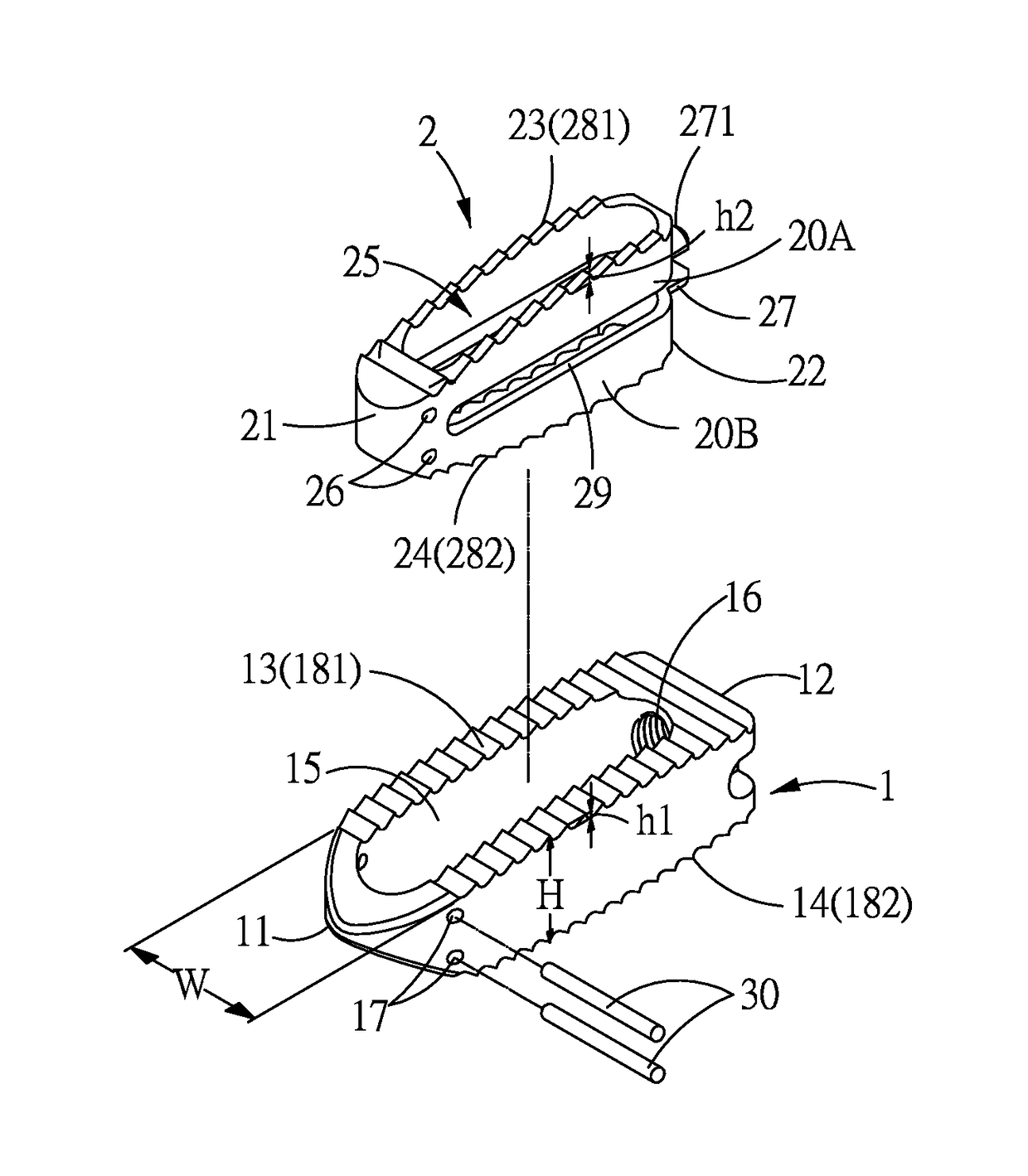
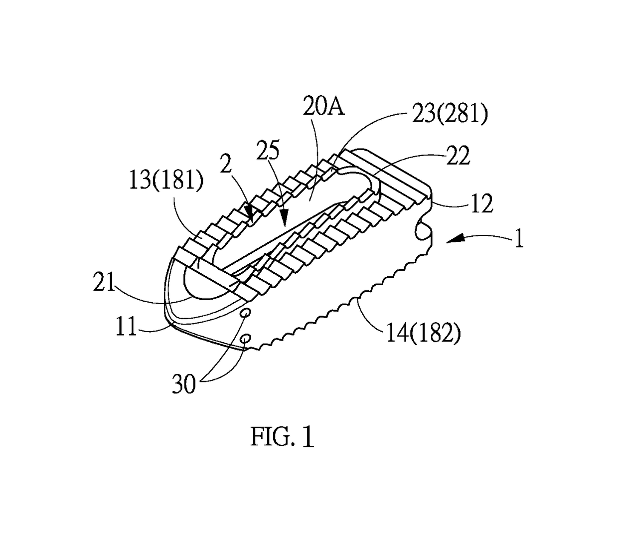
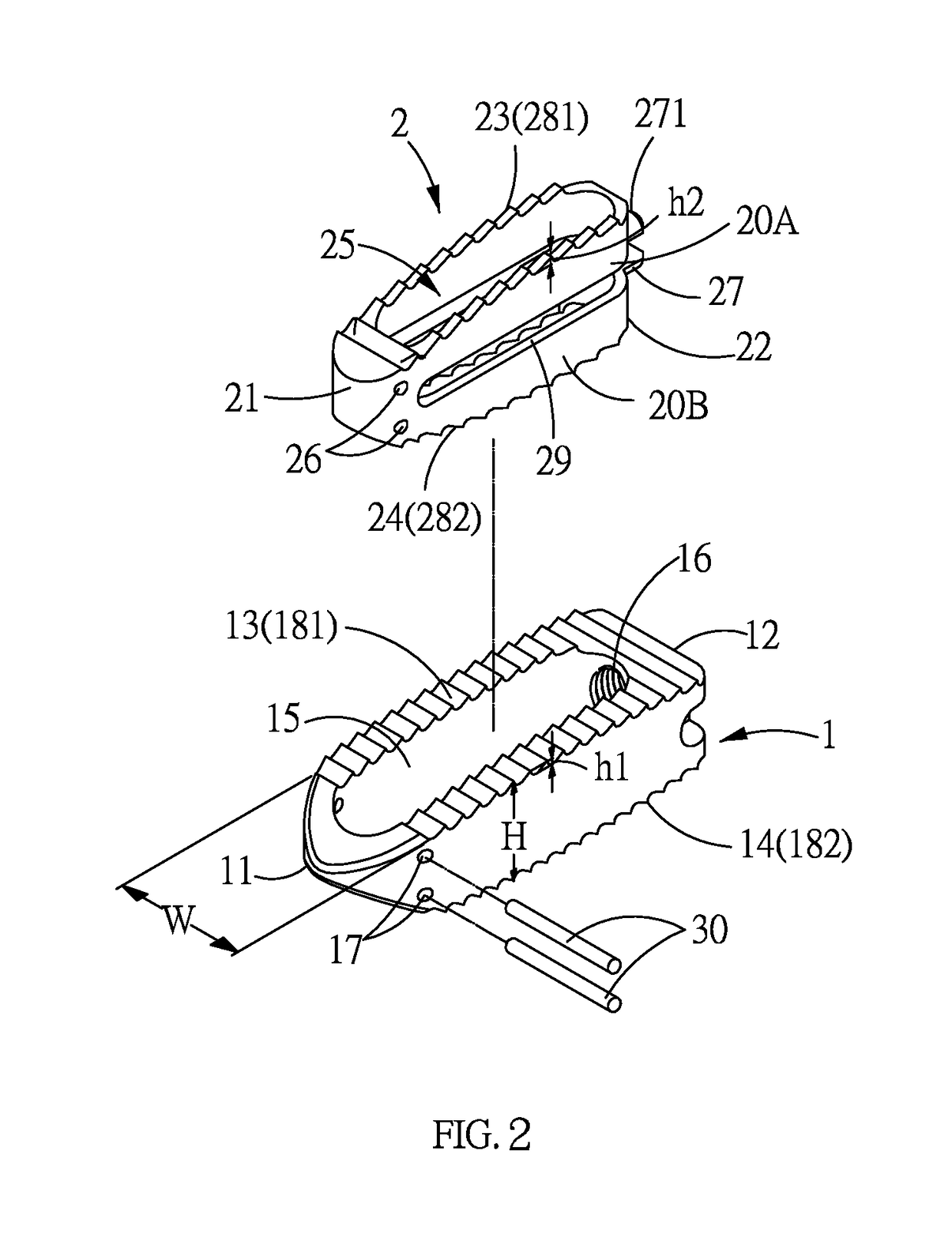
[0025]As shown in FIG. 1 through FIG. 4, the present invention comprises a main body 1 and a movable frame 2.

[0026]The main body 1 has a front end 11 and an opposing rear end 12. The man body 1 further has a raised curved top surface 13 and a raised curved bottom surface 14. The curvatures of the top surface 13 and the bottom surface 14 are close to the curvatures of two adjacent bones S1, S2 (referring to the spines or joints). A height defined by the top surface 13 and the bottom surface 14 is gradually reduced toward the front end 11 and a width defined by left and right sides of the main body 1 is gradually reduced toward the front end 11, enabling the front end 11 to be easily implanted between the two bones S1, S2. The main body 1 further has an accommodation hole 15 which longitudinally penetrates the top surface 13 and the bottom surface 14 an...


PUM


Abstract

A bone fusion device includes a main body and a movable frame. The main body has an accommodation hole. A top surface and a bottom surface of the main body are provided with a plurality of first teeth. The movable frame is located in the accommodation hole. The movable frame has a through hole longitudinally penetrating a first surface and a second surface thereof. A first end of the movable frame is fixed to the front end of the main body, and a second end is suspended relative to the rear end of the main body. The first surface and the second surface are provided with a plurality of second teeth. The movable frame is transversely formed with a groove to define an upper portion and a lower portion, enabling the upper portion and the lower portion to be elastically expanded with the first end as a fulcrum.

Description

BACKGROUND OF THE INVENTION[0001](a) Technical Field of the Invention[0002]The present invention relates to a bone fusion device, and more particularly to a bone fusion device able to generate a micro motion to help bones grow and to provide a stable engagement.[0003](b) Description of the Prior Art[0004]Normally, a bone fusion surgery is used for solving the degeneration of the spinal bones or facet joints due to agedness or other external causes.[0005]As disclosed in Taiwan Patent application number 104208837 titled “spinal fusion device”, 103220076 titled “implantable artificial intervertebral structure”, 100119603 titled “spinal implant and device thereof”, 101202457 titled “cervical vertebra fusion device”, and so on, the teeth on the top and bottom surfaces of a main body provide an acting force for propping two bones (the vertebra or the joints) to a predetermined distance.[0006]Wolff's law states that bone in a healthy person or animal will adapt to the loads under which it ...

Claims


Application Information

Patent Timeline
Patent Type & Authority Patents(United States)
IPC IPC(8): A61F2/44
CPCA61F2/4455A61F2/442A61F2/447A61F2002/4475A61F2220/0008A61F2002/30131A61F2002/30331A61F2002/30563A61F2002/30571A61F2002/30593A61F2002/30904
Inventor HUANG, MAX
Owner OSSAWARE BIOTECH
Learn More