Apparatus and method for treatment of hydraulic fracturing fluid during hydraulic fracturing

Active Publication Date: 2019-11-19
CH INT EQUIP LTD +1
View PDF108 Cites 91 Cited by
  • Summary
  • Abstract
  • Description
  • Claims
  • Application Information

AI Technical Summary

Problems solved by technology

However, it has been found that unlike the proppant entrained in the hydraulic fracturing fluid, gas bubbles are significantly more harmful to these internal pump compo

Method used


Image

  • Apparatus and method for treatment of hydraulic fracturing fluid during hydraulic fracturing
  • Apparatus and method for treatment of hydraulic fracturing fluid during hydraulic fracturing
  • Apparatus and method for treatment of hydraulic fracturing fluid during hydraulic fracturing

Examples


Embodiment Construction

[0013]In the detailed description of the invention, like numerals are employed to designate like parts throughout. Various items of equipment, such as pipes, valves, pumps, fasteners, fittings, etc., may be omitted to simplify the description. However, those skilled in the art will realize that such conventional equipment can be employed as desired.

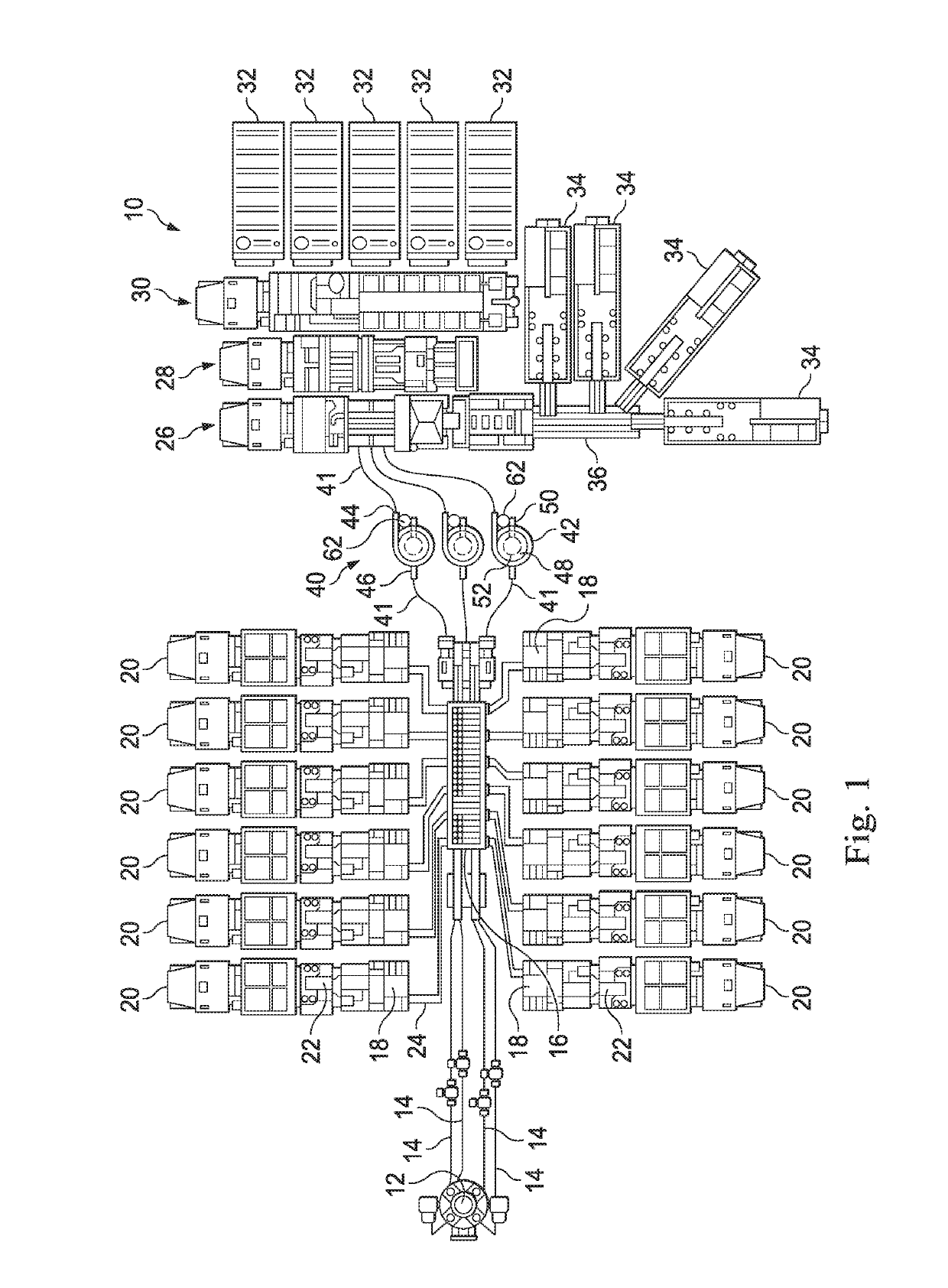
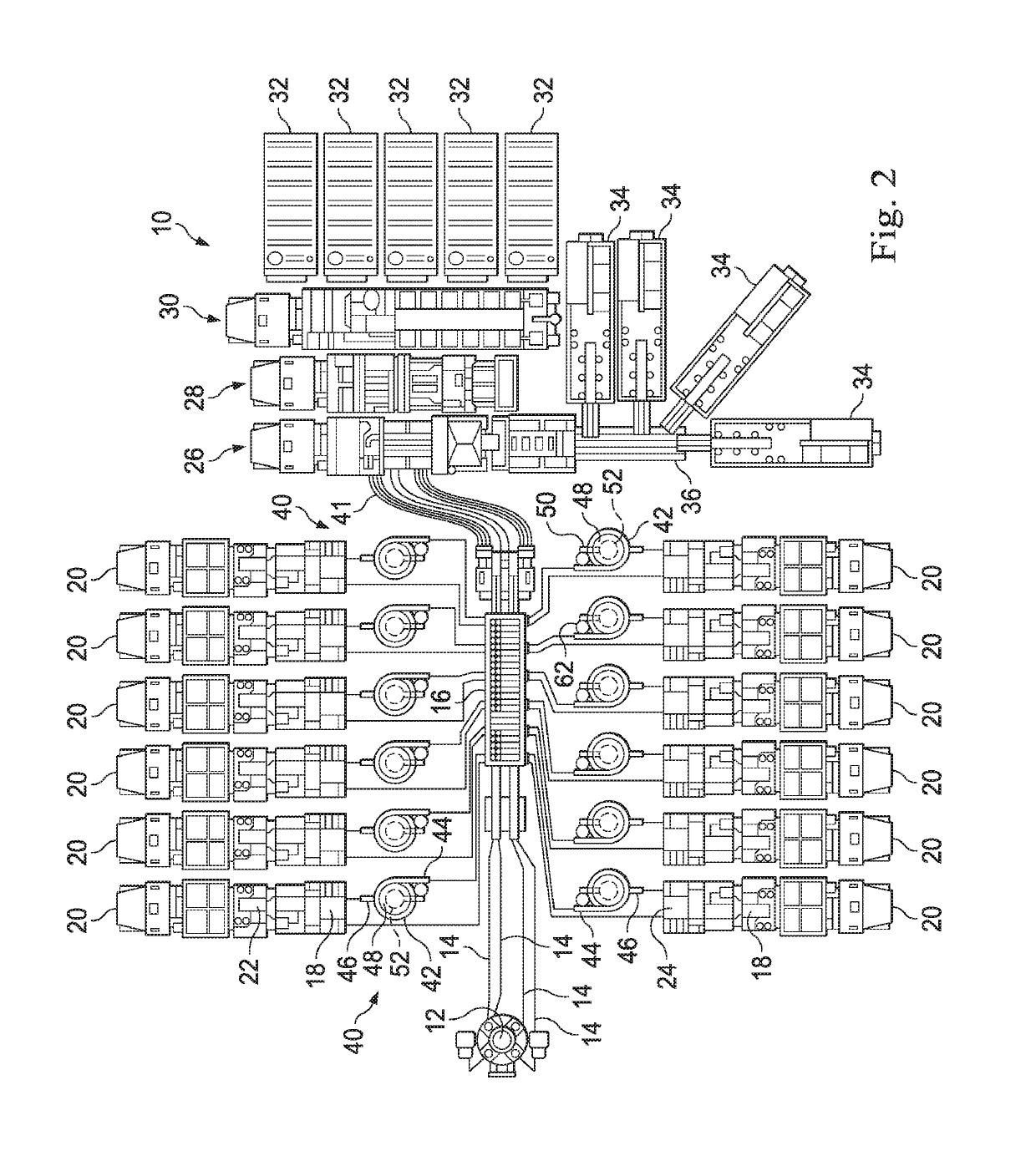
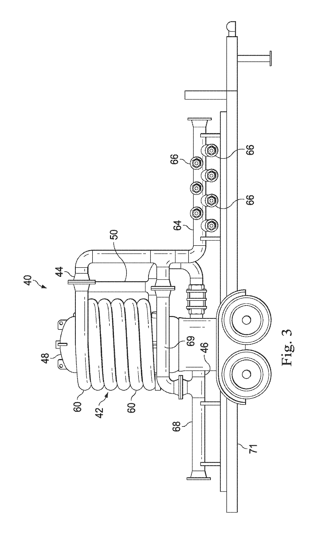
[0014]Generally, a hydraulic fracturing system is provided and may include a liquid source, an additive source, a blender, a high-pressure pump, a hydration unit and a two-phase flow separator system disposed inline between the blender and the high-pressure pump. In some embodiments, the two-phase flow separator system employs a curvilinear flow line system in combination with a fluid vessel to improve operation of the curvilinear flow line system, separating a two-phase fluid into a primarily liquid component and a primarily gaseous component. In one or more embodiments, the curvilinear flow line system is disposed around the outer perim...


PUM

PropertyMeasurementUnit
Pressureaaaaaaaaaa
Pressureaaaaaaaaaa
Diameteraaaaaaaaaa

Abstract

A hydraulic fracturing system utilizes a multi-phase separation apparatus to separate gas entrained in hydraulic fracturing fluids during the blending process prior to introduction of hydraulic fracturing fluid into high pressure fracturing pumps by directing hydraulic fracturing fluids from a blender through a plurality of loops and thereafter, directing a portion of the separated fluid into a vortex cluster system.

Description

FIELD OF THE INVENTION[0001]The present disclosure generally relates to hydraulic fracturing and more particularly, to preparation of hydraulic fracturing fluids prior to injection of the fluids into a formation. Most particularly, the disclosure relates to use of a multi-phase separation apparatus to remove gas bubbles from hydraulic fracturing fluids prior to introduction of the hydraulic fracturing fluids into high pressure hydraulic fracturing pumps.BACKGROUND OF THE INVENTION[0002]During hydraulic fracturing operations utilized in production of hydrocarbons, a proppant, such as sand, is blended in a blending unit with one or more liquids, such as water, to form a hydraulic fracturing fluid. Prior to introduction into the blending unit, the liquids themselves may be mixed together in a hydration unit. In both hydration and blending, air bubbles may become entrained in the fluid as a result of the process. In any event, the hydraulic fracturing fluid is then introduced into a wel...

Claims


Application Information

Patent Timeline
IPC IPC(8): B01D19/00E21B43/26B01F23/80
CPCE21B43/26B01D19/0057E21B43/2607
Inventor ELMS, DAVID JAMESHUDSPETH, GREGORY ALLENCLARK, DONALD PATRICKSKOW, JAMES MICHAEL
Owner CH INT EQUIP LTD
Why Eureka
Try Eureka