Method to automatically adjust a trailer brake controller

a technology for trailer brakes and controllers, applied in the direction of brake action initiation, foot actuation, vehicle components, etc., can solve the problems of brake gain adjustment not being responsive enough for a user to make adjustments during extended driving over varying speeds, brake gain not being responsive enough for extended driving,

Active Publication Date: 2019-11-19
FORD GLOBAL TECH LLC
View PDF22 Cites 2 Cited by
  • Summary
  • Abstract
  • Description
  • Claims
  • Application Information

AI Technical Summary

Problems solved by technology

While such systems may provide for adjustment of a gain applied to the brake torque demand signal to achieve the output trailer brake control signal, this gain adjustment is not responsive enough for a user to make adjustments during extended driving over varying speeds.
In some instances, a user may forget to adjust gain when needed, resulting in extended driving with either too little or too much trailer brake torque during braking.
Further, as the overall brake torque (vehicle brakes and trailer brakes) needed to slow the combined vehicle and trailer varies with the speed of the combined vehicle and trailer (e.g., by requiring higher deceleration to slow over a comparable distance) and with road grade, a constant brake gain may result, for example, in excessive gain leading to wheel locking during braking from relatively lower speeds (e.g., less than 5 miles per hour).

Method used


Image

  • Method to automatically adjust a trailer brake controller
  • Method to automatically adjust a trailer brake controller
  • Method to automatically adjust a trailer brake controller

Examples


Embodiment Construction

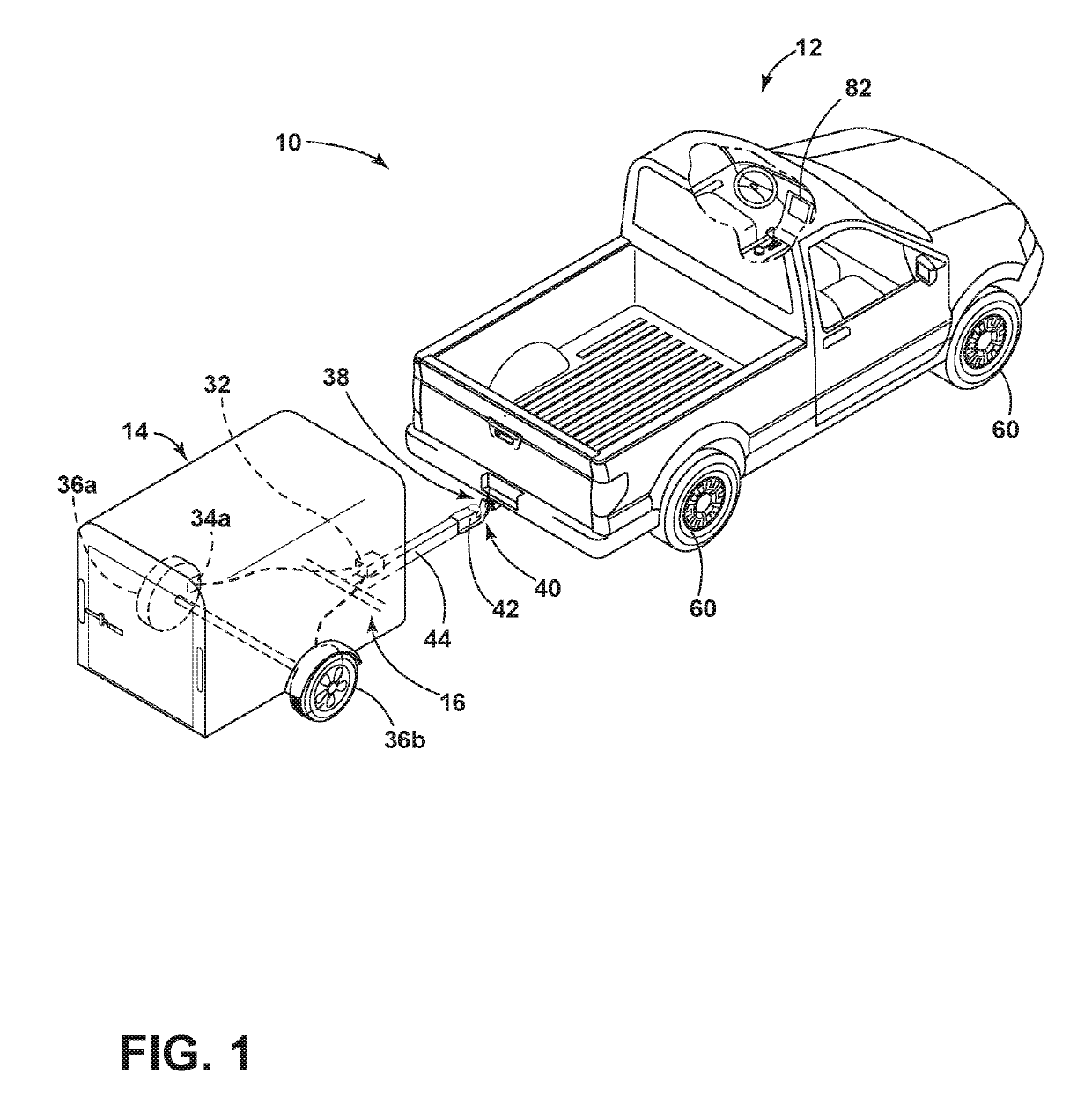
[0024]For purposes of description herein, the terms “upper,”“lower,”“right,”“left,”“rear,”“front,”“vertical,”“horizontal,”“interior,”“exterior,” and derivatives thereof shall relate to the device as oriented in FIG. 1. However, it is to be understood that the device may assume various alternative orientations, except where expressly specified to the contrary. It is also to be understood that the specific devices and processes illustrated in the attached drawing, and described in the following specification are simply exemplary embodiments of the inventive concepts defined in the appended claims. Hence, specific dimensions and other physical characteristics relating to the embodiments disclosed herein are not to be considered as limiting, unless the claims expressly state otherwise. Additionally, unless otherwise specified, it is to be understood that discussion of a particular feature of component extending in or along a given direction or the like does not mean that the feature or ...


PUM


Abstract

A vehicle brake system includes a brake control device, a vehicle acceleration sensor, and a trailer brake controller. The trailer brake controller outputs an initial trailer brake torque demand based on an input received from the brake control device and adjusts the initial trailer brake torque demand to converge a signal from the vehicle acceleration sensor to an expected negative acceleration value correlated with the input from the brake control device.

Description

FIELD OF THE DISCLOSURE[0001]The present disclosure generally relates to a system for control of trailer brakes by a towing vehicle. In particular, the system adjusts a control signal for the trailer brakes to achieve an expected deceleration rate of the vehicle-trailer combination.BACKGROUND OF THE DISCLOSURE[0002]Control systems have been used within vehicles to control trailer brakes. Such systems generally activate in a manner correlated with actuation of the vehicle brakes to augment the braking force of the vehicle itself, which may be necessary or useful for towing larger or heavier trailers. Known systems provide a control signal for a coupled trailer brake system that is constantly proportional to the torque demand of the vehicle brakes (i.e. the position of the vehicle brake pedal), regardless of the actual braking effect achieved by the controlled actuation of the trailer brakes. While such systems may provide for adjustment of a gain applied to the brake torque demand si...

Claims


Application Information

Patent Timeline
Patent Type & Authority Patents(United States)
IPC IPC(8): B60T8/17B60T8/172B60T7/20B60T8/32B60T7/04B60T8/176
CPCB60T8/1708B60T8/321B60T7/042B60T8/176B60T7/20B60T8/172B60T8/248B60T8/323B60T13/662B60T13/686
Inventor HILL, THADDEUSBOUSAMRA, JOE ALEXANDERRHEIN, LAWRENCE ROBERT
Owner FORD GLOBAL TECH LLC
Why Eureka
Try Eureka