Piezoresistive pressure sensor provided with a calibration resistor of the offset

a piezoresistive pressure sensor and offset calibration technology, applied in the direction of fluid pressure measurement by electric/magnetic elements, measuring devices, instruments, etc., can solve the problems of high cost, complicated calibration of pressure sensors, and high cost of pressure sensors, so as to achieve simple and economical way, easy calibration, and precise and accurate measurement

Active Publication Date: 2019-11-19
KOLEKTOR MICROTEL SRL
View PDF5 Cites 3 Cited by
  • Summary
  • Abstract
  • Description
  • Claims
  • Application Information

AI Technical Summary

Benefits of technology

[0014]In the scope of this technical task, an aim of the invention is to provide a piezoresistive pressure sensor that can be manufactured in a simple and economical way.
[0015]Another object of the invention is to provide a piezoresistive pressure sensor that is easy to calibrate.
[0016]Another object of the invention is to provide a piezoresistive pressure sensor that is constructionally simple, mechanically resistant, precise and accurate in measuring and a deterioration of which is minimised throughout its working life.

Problems solved by technology

Owing to the presence of the calibration resistor, the pressure sensor has a production process that is very complex and consequently expensive, especially for the carrying out of the electrical connection between the calibration resistor and the rest of the resistive bridge.
Moreover the calibrating of the pressure sensor is rather complicated as it requires a delicate choice of the point of the calibration resistor at which to carry out a precise and accurate laser cut.
Further, the need to calibrate the pressure sensor after assembly thereof means that the calibration resistor must remain in an accessible position and therefore also exposed to the risk of damage.

Method used


Image

  • Piezoresistive pressure sensor provided with a calibration resistor of the offset
  • Piezoresistive pressure sensor provided with a calibration resistor of the offset
  • Piezoresistive pressure sensor provided with a calibration resistor of the offset

Examples


Embodiment Construction

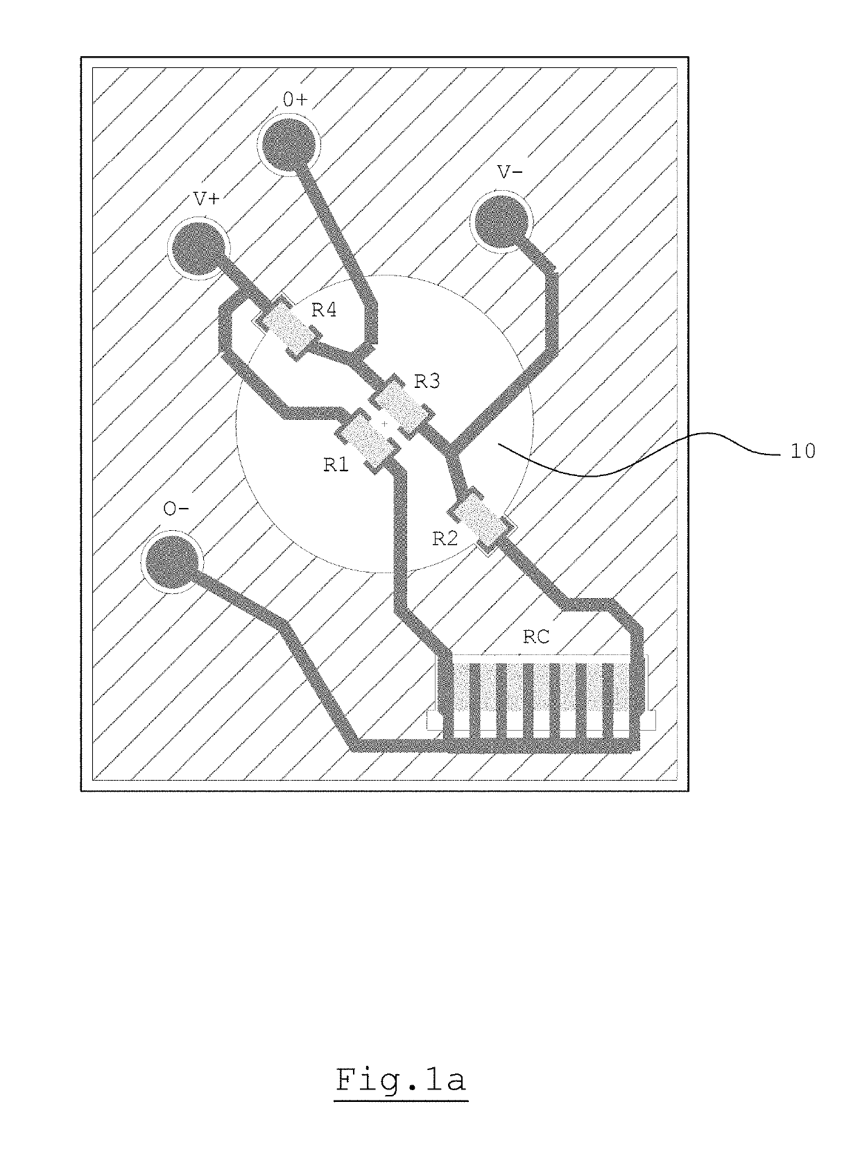
[0046]With reference to the appended figures, a piezoresistive pressure sensor is illustrated, generally indicated by numeral reference 1.

[0047]The pressure sensor 1 comprises a rigid flat support 2, formed in particular but not necessarily by a slab made of ceramic material having a circular, rectangular or even another shape, and a flat flexible membrane 3, formed in particular but not necessarily by a slab made of ceramic material that is thinner than the preceding slab and circular or even another shape.

[0048]The membrane 3 has a flat external face 4 exposed to the pressure to be measured of a fluid and a flat internal face 5.

[0049]The support 2 has an external face 6 and an internal face 7.

[0050]The internal face 7 of the support 2 and the internal face 5 of the membrane 3 are facing one another and, in cooperation with one another and with a glass layer 8 perimetrally interposed between them for reciprocal connection delimit a chamber 9 accommodating the deformation of the act...


PUM

PropertyMeasurementUnit
pressureaaaaaaaaaa
flexibleaaaaaaaaaa
resistanceaaaaaaaaaa

Abstract

The piezoresistive pressure sensor (1) comprises a rigid flat support (2), a flat flexible membrane (3) having a flat external face (4) exposed to a pressure of a fluid and a flat internal face (5) delimiting in cooperation with a flat internal face (7) of the support (2) a chamber (9) accommodating the deformation of the membrane (3), an electrical measuring circuit comprising a resistive Wheatstone bridge (10) applied on the flat internal face (5) of the membrane (3) for detecting the deformation of the membrane (3), and at least an electrical resistor (Rc) for calibrating the value of the output signal when the fluid is at a reference pressure, the calibration resistor (Rc) being applied on the flat internal face (5) of the membrane (3).

Description

RELATED APPLICATIONS[0001]This application claims priority to Italy Application No. 102016000081649, filed Aug. 3, 2016. The above-identified related application is incorporated by reference.FIELD OF USE[0002]The present invention relates to a flat piezoresistive pressure sensor.BACKGROUND OF THE INVENTION[0003]In various sectors, such as industry, medicine and motor vehicles, use is known of piezoresistive pressure sensors incorporated in a transducer for measuring a pressure of a fluid.[0004]A flat piezoresistive pressure sensor generally comprises a rigid flat support made of a ceramic material, a flat flexible membrane made of a ceramic material having a flat external face exposed to a pressure of a fluid and a flat internal face delimiting, in cooperation with a flat internal face of the support, a chamber accommodating a deformation of the membrane, a resistive Wheatstone bridge applied on the flat internal face of the membrane for detecting the deformation thereof.[0005]One o...

Claims


Application Information

Patent Timeline
Patent Type & Authority Patents(United States)
IPC IPC(8): G01L9/00G01L27/00
CPCG01L9/0055G01L27/002G01L27/005G01L9/0052
Inventor MAY, ROBERTOBERSANI, ERMINIO MARIASUVIGHI, PAOLO PIETRO
Owner KOLEKTOR MICROTEL SRL
Why Eureka
Try Eureka