Brake control device for injection molding machine and brake control method for injection molding machine

a technology of brake control device and injection molding machine, which is applied in the direction of brake control device for injection molding machine and brake control method for injection molding machine, can solve the problems of damage or breakage of the brake mechanism, and achieve the effect of preventing the brake mechanism from being deteriorated or broken, and ensuring the safety of the operator

Active Publication Date: 2019-12-10
FANUC LTD
View PDF7 Cites 0 Cited by
  • Summary
  • Abstract
  • Description
  • Claims
  • Application Information

AI Technical Summary

Benefits of technology

[0005]It is therefore an object of the present invention to provide a brake control device for an injection molding machine that suppresses deterioration or breakage of a brake mechanism that applies a braking force to a mold opening / closing mechanism as well as providing a brake control method for an injection molding machine.

Problems solved by technology

This load accompanying the release of the mold clamping force is large, which may damage or break the brake mechanism.

Method used


Image

  • Brake control device for injection molding machine and brake control method for injection molding machine
  • Brake control device for injection molding machine and brake control method for injection molding machine
  • Brake control device for injection molding machine and brake control method for injection molding machine

Examples


first embodiment

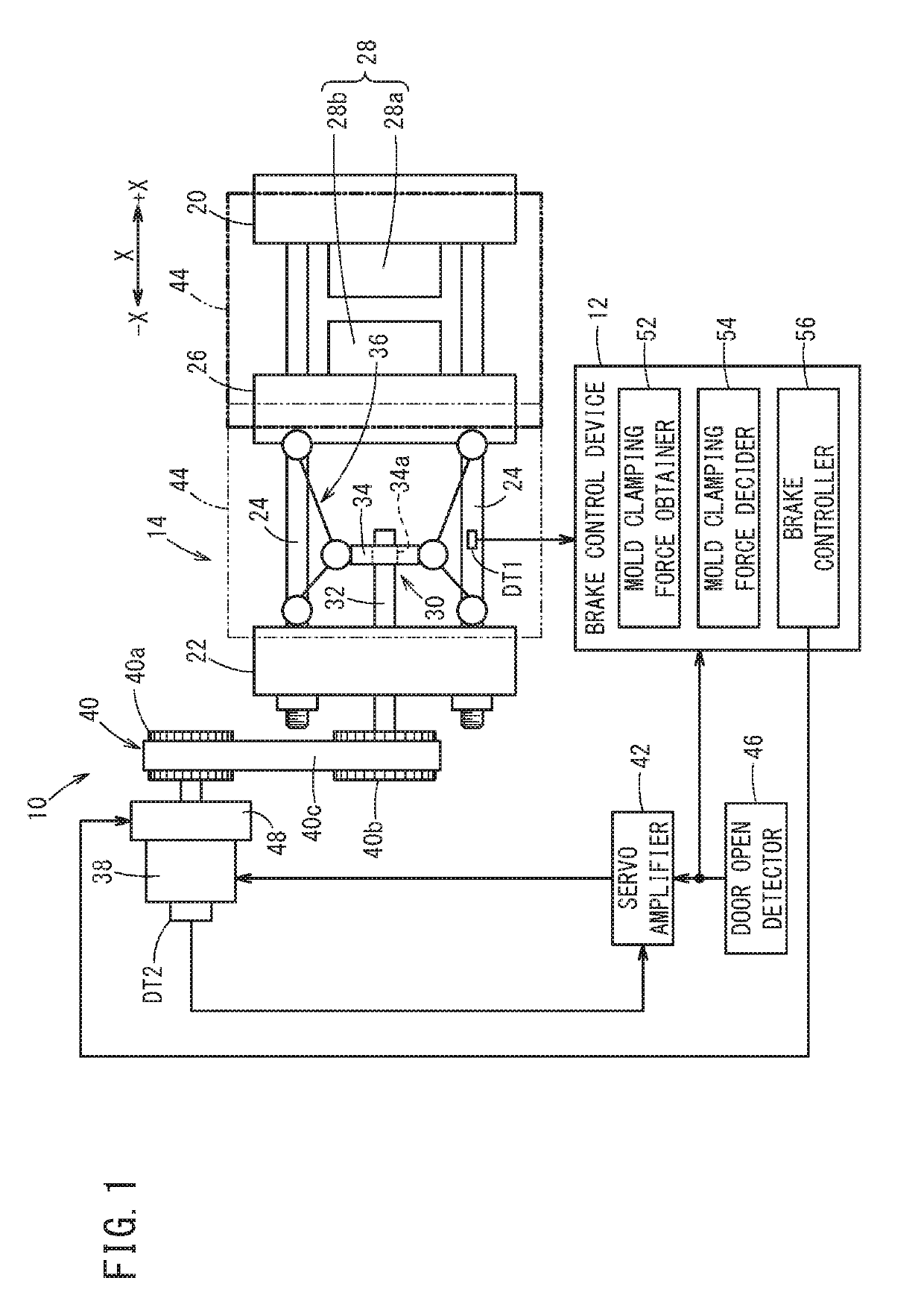
[0015]FIG. 1 is a schematic configuration diagram of an injection molding machine 10 and a brake control device 12 for the injection molding machine 10. A mold clamping unit 14 of the injection molding machine 10 has a stationary platen 20, a rear platen 22 and four tie bars 24. The four tie bars 24 connect the stationary platen 20 and the rear platen 22. The four tie bars 24 are arranged so that their axial directions are parallel to the X-direction. A moving platen 26 is provided between the stationary platen 20 and the rear platen 22. The moving platen 26 can move in the axial directions (X-directions) of the tie bars 24 along the four tie bars 24.

[0016]A mold 28 is attached between the stationary platen 20 and the moving platen 26. The mold 28 is composed of a stationary mold half 28a and a moving mold half 28b. The stationary mold half 28a is attached to the stationary platen 20 on the side facing moving platen 26, and the moving mold half 28b is attached to the moving platen 2...

##al examples

VARIATIONAL EXAMPLES

[0041]The above embodiment can be modified as follows.

##al example 1

Variational Example 1

[0042]Though in the above embodiment, the mold clamping force detector DT1 for directly detecting the mold clamping force of the mold opening / closing mechanism 30 is provided, a rotational position detector DT2 for detecting the rotational position of the servomotor 38 may be used instead of the mold clamping force detector DT1. Alternatively, instead of the mold clamping force detector DT1, a torque detector DT3 for detecting the torque generated in the servomotor 38 or a position detector DT4 for detecting the position of the ball screw 32 of the crosshead 34 with respect to the axial direction may be used, as shown in FIG. 4.

[0043]Use of the rotational position detector DT2 for detecting the rotational position of the servomotor 38 makes it possible to know the position of the crosshead 34 in the axial direction of the ball screw 32, which provides information on the mold clamping force of the mold opening / closing mechanism 30. Alternatively, use of the posit...


PUM

PropertyMeasurementUnit
clamping forceaaaaaaaaaa
forceaaaaaaaaaa
mold clamping forceaaaaaaaaaa

Abstract

A brake control method for an injection molding machine includes the steps of obtaining mold clamping force information indicating the mold clamping force of a mold opening / closing mechanism and determining whether or not the mold clamping force of the mold opening / closing mechanism exceeds a predetermined value, based on the mold clamping force information. When the mold clamping force of the mold opening / closing mechanism does not exceed the predetermined value and when a servo amplifier cuts off the supply of power to a servomotor that drives the mold opening / closing mechanism, a brake mechanism for applying braking force to the mold opening / closing mechanism is actuated. On the other hand, when the mold clamping force of the mold opening / closing mechanism exceeds the predetermined value, the brake mechanism will not be actuated.

Description

CROSS-REFERENCE TO RELATED APPLICATION[0001]This application is based upon and claims the benefit of priority from Japanese Patent Application No. 2017-152511 filed on Aug. 7, 2017, the contents of which are incorporated herein by reference.BACKGROUND OF THE INVENTIONField of the Invention[0002]The present invention relates to a brake control device for an injection molding machine that applies a braking force to a mold opening / closing mechanism for opening and closing a mold and a brake control method for an injection molding machine.Description of the Related Art[0003]Japanese Laid-Open Patent Publication No. 2013-014054 discloses a brake unit that limits rotation of a motor unit when no current is supplied to the motor unit for opening and closing a mold.SUMMARY OF THE INVENTION[0004]When the safety door of the injection molding machine opens, power supply to the motor for driving the mold opening / closing mechanism is stopped. Therefore, when the safety door is opened while the c...

Claims


Application Information

Patent Timeline
Patent Type & Authority Patents(United States)
IPC IPC(8): B29C45/76B29C45/84B29C45/66B29C45/17
CPCB29C45/7653B29C45/84B29C45/66B29C2045/1792B29C2945/76391B29C45/661B29C2945/76505B29C2045/665B29C2945/76448B29C2945/76013B29C2945/76869B29C2945/76344
Inventor UCHIYAMA, TATSUHIROMARUYAMA, JUNPEITANAKA, KAZUYOSHI
Owner FANUC LTD
Why Eureka
Try Eureka