Dynamic brake force indicator

a technology of brake force and indicator, which is applied in the direction of brake safety systems, brake systems, transportation and packaging, etc., can solve the problems that the operator of a trailing vehicle cannot safely maneuver to avoid a rear end, and the simple brake indication may not be enough to achieve the effect of facilitating a dynamic display of brake force and high level of safety

Active Publication Date: 2019-12-10
THUNDER POWER NEW ENERGY VEHICLE DEV CO LTD
View PDF14 Cites 0 Cited by
  • Summary
  • Abstract
  • Description
  • Claims
  • Application Information

AI Technical Summary

Benefits of technology

[0004]Embodiments can facilitate a dynamic display of brake force applied to a brake pedal in a driving apparatus. A high level of safety can be achieved if the operator of the trailing driving apparatus is alerted to a degree of brake force applied by the driving apparatus in front. In some embodiments, a pedal force sensor capable of determining an amount of brake force applied to a brake pedal can be employed. In those embodiments, the pedal force sensor can be attached to the top of the brake pedal in the driving apparatus. The pedal force sensor at the brake pedal can measure and record applied brake forces. A degree of the applied brake force relative to a maximum brake force that can be applied to the brake pedal can be determined. The degree of the applied brake force can be dynamically and visually displayed so that the operator of trailing driving apparatus can be aware of how strong the brake force applied by the driving apparatus in front. In those embodiments, the dynamic display of the applied brake force can include altering the illumination intensity, illumination area, frequency, and / or any other illumination parameters according to the brake force applied by the driving apparatus. In some embodiments, the dynamic display of the brake force is achieved through one or more rearward facing OLED lamps mounted at the back of the driving apparatus.

Problems solved by technology

This simple brake indication however may not be enough for the operator of a trailing vehicle to safely maneuver to avoid a rear end collision.

Method used


Image

  • Dynamic brake force indicator
  • Dynamic brake force indicator
  • Dynamic brake force indicator

Examples


Embodiment Construction

[0014]In the following description, various embodiments will be described. For purposes of explanation, specific configurations and details are set forth in order to provide a thorough understanding of the embodiments. However, it will also be apparent to one skilled in the art that the embodiments may be practiced without the specific details. Furthermore, well-known features may be omitted or simplified in order not to obscure the embodiment being described.

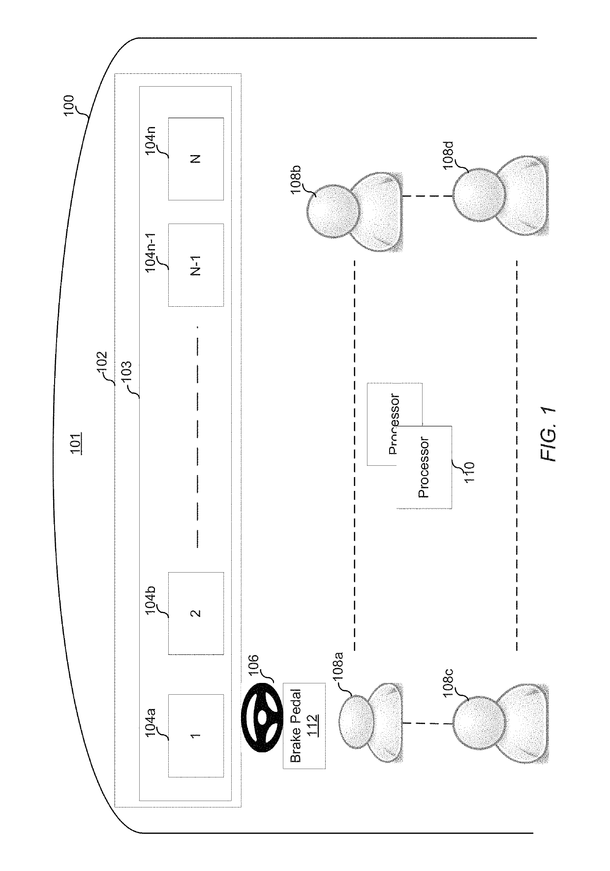
[0015]FIG. 1 generally illustrates an example of a driving apparatus 100 in accordance with the disclosure. The driving apparatus 100 may include any apparatus that moves in distance. Examples of driving apparatus 100 may include a vehicle such as a car, a bus, a train, a truck, a tram, or any other type of vehicle; may include a vessel such as a boat, a ship, a barge, a ferry or any other type of watercraft; may include an aircraft such as an airplane, a spaceship, or any other type of aircraft; or may include any other transp...


PUM


Abstract

Dynamically displaying of a brake force is disclosed. A brake pedal force sensor can be used to generate signals indicating an amount or a level of brake force exerted on a brake pedal of a driving apparatus. Such signals can be processed to determine degrees of the brake force exerted. A set of display parameter values can be determined based on the determined degree of the brake force. The set of display parameters can include at least one value for illumination brightness, illumination area, illumination frequency, illumination color, and / or illumination style on a brake light of the driving apparatus. In certain embodiments, the display of the brake force is in a form of sliding bar and / or circular ring, and the brightness and / or the illumination area of the brake light is proportional to the determined degree of the brake force.

Description

CROSS-REFERENCE TO RELATED APPLICATIONS[0001]The present application claims priority to U.S. Provisional Patent Application No. 62 / 272,716, filed on Dec. 30, 2015, the disclosure of which is hereby incorporated by reference in its entirety for all purposes.FIELD[0002]The present invention relates to vehicle brake light systems and, more particularly, to brake light systems in which brake lights at the rear of a vehicle are illuminated in response to depression of a brake pedalBACKGROUND[0003]Most vehicles are equipped with rearward facing visual signaling devices to indicate when the vehicles braking system is activated. Conventional brake systems in a vehicle typically operate when a brake pedal switch is closed and the vehicle is still in motion and a row of lamps at the rear of the vehicle are illuminated to simply indicate that the braking system is activated. This simple brake indication however may not be enough for the operator of a trailing vehicle to safely maneuver to avoi...

Claims


Application Information

Patent Timeline
Patent Type & Authority Patents(United States)
IPC IPC(8): B60T17/22B60Q1/44B60T7/04
CPCB60Q1/444B60T7/042B60T17/22B60Q1/441
Inventor DING, JIA-WEI
Owner THUNDER POWER NEW ENERGY VEHICLE DEV CO LTD
Why Eureka
Try Eureka