Plate for osteosynthesis

a plate and osteosynthesis technology, applied in the field of osteosynthesis plates, can solve the problems of loss of time, difficult deformation of plates, deformation of plates, etc., and achieve the effects of optimal fixation of plates, simple and rapid fixation of plates, and minimizing the risk of any play

Active Publication Date: 2019-12-17
NEOSTEO
View PDF9 Cites 0 Cited by
  • Summary
  • Abstract
  • Description
  • Claims
  • Application Information

AI Technical Summary

Benefits of technology

[0040]The invention particularly permits good congruence on the epiphysis portion in the case of a use as an addition plate and as a subtraction plate, while at the same time being easy to manipulate and fix.
[0080]Titanium is able to give the plate significant advantages in terms of strength, durability, and safety for the patient.

Problems solved by technology

However, the use of a deformable plate has its limitations, for several reasons, among which:the adaptation of the plate to the shape of the bone is difficult and depends on the skill and experience of the surgeon;the deformation of a plate is more difficult, or even impossible, in certain directions, especially in the case of plates having a small width;the deformation of the plate supposes the use of additional tools during an operation, hence their prior sterilization;the operation of deforming the plate and then placing the deformed plate on the bone often has to be repeated several times by the surgeon before he proceeds to fix it, which causes a loss of time and needlessly prolongs the period of anesthesia of the patient;the deformations made to the plate have a tendency to weaken it or even instigate breaks.
When he fits a non-deformable plate on the bone, there is a good chance of the surgeon having to fix it in a position in which it does not bear satisfactorily on the epiphysis, since the cylindrical shape of the head considerably limits the possibilities the surgeon has to adjust the position of the plate.
However, they require numerous screws in different directions and are not easy to use.
However, experience has shown that this result was entirely satisfactory and that the patient did not experience any pain as a consequence.

Method used


Image

  • Plate for osteosynthesis
  • Plate for osteosynthesis
  • Plate for osteosynthesis

Examples


Embodiment Construction

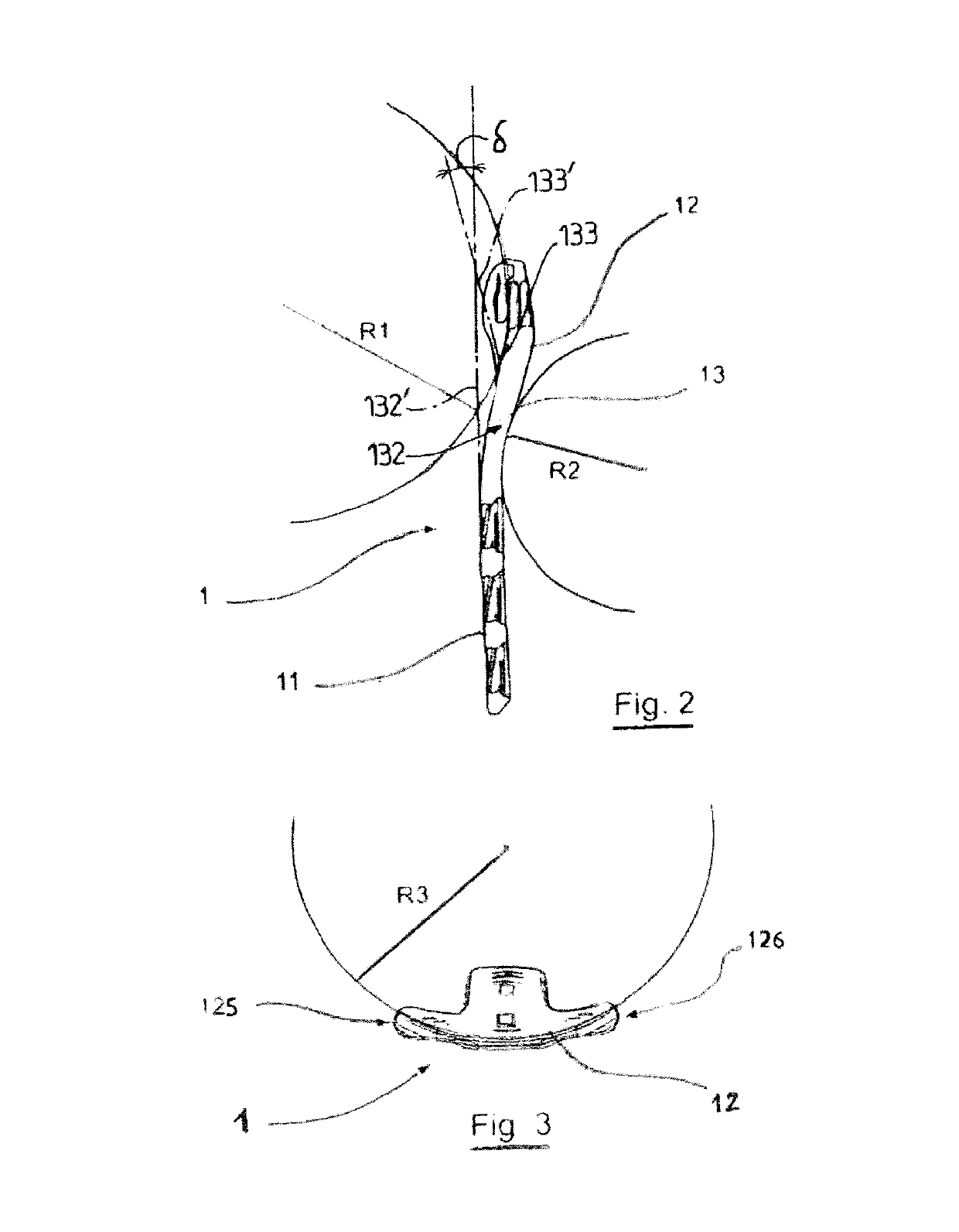
[0097]As has been indicated above, one of the principles of the invention is to make available an osteosynthesis plate which is non-deformable at ambient temperature and which has a foot intended to be connected to the diaphysis of a bone and has a head intended to be connected to an epiphysis of the same bone, such that the head has a continuously curved profile, when viewed from above and also when viewed from the side, while permitting easy adjustment by virtue of the other features described hereinbelow.

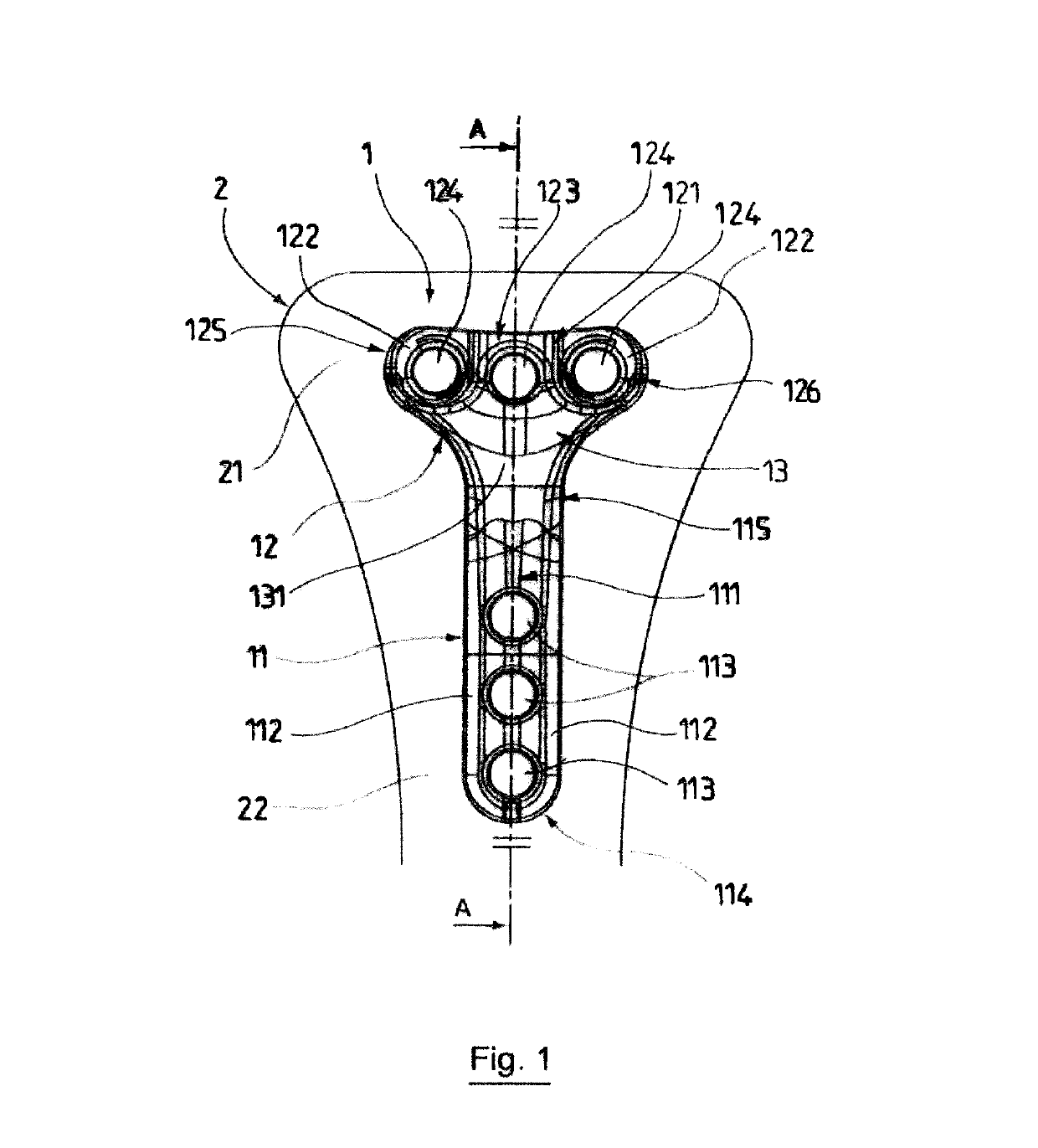
[0098]Referring to FIG. 1, a plate 1 according to the invention is shown in front of a bone 2, on which it is intended to be fixed.

[0099]The bone 2 illustrated is a long bone, shown in part here, specifically in the area of one of its epiphyses 21 and as far as its diaphysis 22.

[0100]The plate 1 is rigid and non-deformable at ambient temperature. Thus, during an operation performed by a surgeon, it is connected to the bone 2 without undergoing deformation.

[0101]The plate 1 is mad...


PUM


Abstract

A T-shaped plate for osteosynthesis, has at least three first attachment holes (124) and second attachment holes (113) including a curved linkage area (13). The epiphysis portion has a recess (34) with a curved profile from one end to the other of the T-bar when viewed from the top, and a curved profile when viewed from the side, and the diaphysis portion is straight and rigid. The plate is non-deformable at normal temperatures. The leg of the T has a rounded inner surface (56). The linkage area (13) has an S-shaped longitudinal cross-section, the ends (132, 133) of which that are adjoined with the bar and leg of the T, respectively, are substantially parallel to one another.

Description

BACKGROUNDField of the Invention[0001]The invention relates to an osteosynthesis plate.[0002]It also relates to a device and a method using such a plate which is to be applied to at least part of a bone.[0003]This type of plate is not only intended to come into direct contact with the bone (by contrast to the plates which are used to bring together or even compress two bone fragments, by way of fixation screws or rods, and which are therefore not necessarily in contact with the bone) but can also have a shape corresponding at least partially to the external shape of the bone.[0004]It has an application particularly but not exclusively in the field of design and production of osteosynthesis equipment and, more precisely, of plates intended to be connected to and in contact with a long bone at several points thereof.[0005]A plate within the field of the invention can be used in particular in an osteotomy operation, the aim of which may be, for example, to modify the structure of a sup...

Claims


Application Information

Patent Timeline
Patent Type & Authority Patents(United States)
IPC IPC(8): A61B17/80
CPCA61B17/8052A61B17/8095A61B17/8057A61B17/8028A61B17/8061
Inventor CHATAIN, FREDERICDENJEAN, STEPHANEGAILLARD, THIERRYDELALANDE, JEAN-LUCCHAVANE, HERVECARRET, JEAN-PAULBEJUI, JACQUESGUYEN, OLIVIERTAYOT, OLIVIERPIBAROT, VINCENTDEROUET, GUILLAUMEGAYRAUD, BENOIT
Owner NEOSTEO
Why Eureka
Try Eureka