
Adaptive impedance power amplifier

a power amplifier and impedance technology, applied in power amplifiers, amplifiers, amplifier input/output impedence modification, etc., can solve the problems of linearity performance degradation cost and limited methods, and achieve high efficiency, low efficiency, and high efficiency.

Active Publication Date: 2019-12-17
GEPSTEIN OFER
View PDF10 Cites 2 Cited by
  • Summary
  • Abstract
  • Description
  • Claims
  • Application Information

AI Technical Summary

Benefits of technology

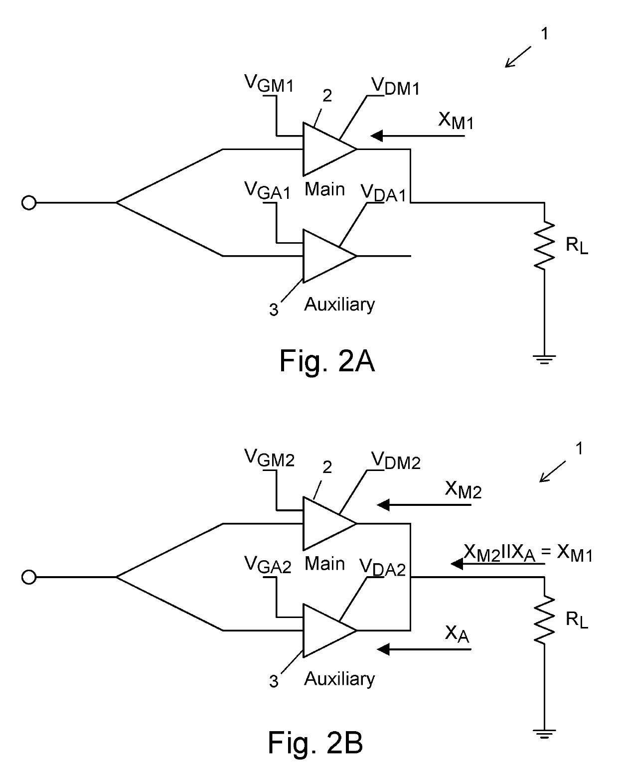
[0018]According to an embodiment of the invention, the output impedance maintain constant by choosing Vd and Vg in a way, that one amplifier will compensate the distortion of the second amplifier (Main to Auxiliary and vice versa).
[0027]According to an embodiment of the invention, during power interval, one transistor is being used as a main transistor, when the rest of the transistors are being used as a power linearize and / or phase linearize, and / or as efficiency improving.
[0030]According to an embodiment of the invention, the power supply voltage amplitude of the main amplifier is lower in compare to a single transistor envelope tracking, and the main amplifier reach high efficiency even before that envelop tracking is active, as the power supply modulator efficiency is a function of the power drop, with low efficiency at backoff and higher efficiency at the peak levels, efficiency is gained.

Problems solved by technology

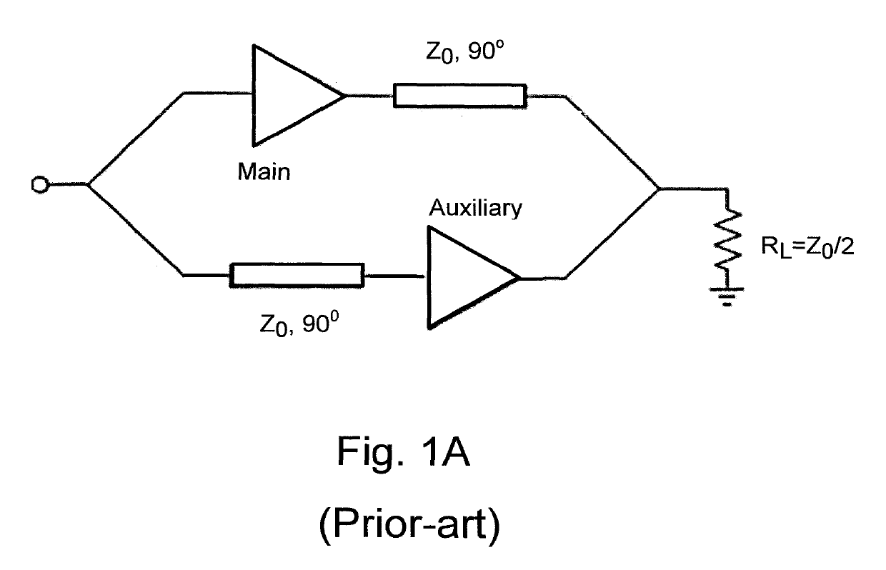
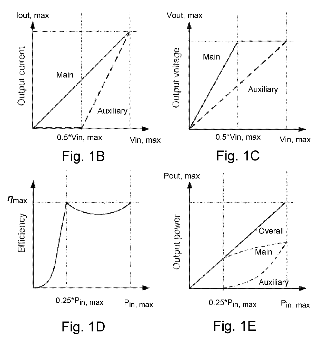
Moreover, the Doherty PA that is based on transistors such as FET's can truly provide a superior improvement of efficiency, but with the cost of some degradation in linearity performances.
However, this method is limited due to the change of the transistor impedance in function of the Drain voltage level.

Method used


Image

  • Adaptive impedance power amplifier
  • Adaptive impedance power amplifier
  • Adaptive impedance power amplifier

Examples


Embodiment Construction

[0050]Reference will now be made to several embodiments of the present invention, examples of which are illustrated in the accompanying figures. Wherever practicable similar or like reference numbers may be used in the figures and may indicate similar or like functionality. The figures depict embodiments of the present invention for purposes of illustration only. One skilled in the art will readily recognize from the following description that alternative embodiments of the structures and methods illustrated herein may be employed without departing from the principles of the invention described herein.

[0051]In class A the impedance of a transistor that can be seen by the load is varied by the power source in a simple manner:

[0052]Rds=VdsIds(1)

[0053]Assuming at class A that ids (Alternative Current—AC) variation is small, we can take Ids (Direct Current—DC) as a constant. Therefore, Rds is a linear function of Vds. Since at thot class of operation, the goal is to match the load to th...


PUM


Abstract

The present invention relates to a method, of providing adaptive impedance in a Power Amplifier (PA), by providing more than one transistors in which one transistor is used to change the load line or to linearize the input signal by adapting the biasing of each transistor, wherein the transistors are connected in parallel.

Description

FIELD OF THE INVENTION[0001]The present invention relates to the field of Radio Frequency (RF) communication systems. More particularly, the invention relates to an adaptive impedance Power Amplifier (PA) system for providing linearity and efficiency enhancement.BACKGROUND OF THE INVENTION[0002]Linear power amplifiers that can maintain high efficiencies over wide ranges of output power levels are key components in modern communication systems. Achieving high efficiencies at back-off power levels is important both in base and mobile stations since the former must handle multi-carrier signals with high peak-to-average power ratios (high PARs) and the latter often should operate at low powers to maximize the battery lifetime. On the other hand, these amplifiers must meet stringent linearity requirements to keep the out of band spectral emissions within the Federal Communications Commission (FCC) recommended spectral masks. In addition, with the growth of the quantity of data transfer t...

Claims


Application Information

Patent Timeline
Patent Type & Authority Patents(United States)
IPC IPC(8): H03F1/02H03F3/21H03F3/193H03F1/32H03F1/56
CPCH03F1/56H03F1/0266H03F1/0205H03F1/0288H03F1/32H03F3/21H03F3/193H03F1/3205H03F2200/18H03F2200/15H03F2200/451H03F2200/102
Inventor GEPSTEIN, OFER
Owner GEPSTEIN OFER
Learn More