
Adaptive compensation for measurement distortions in spectroscopy

a spectroscopy and distortion technology, applied in the field of data capture and analysis, can solve the problems of distortion-related components of measurement variation, and current practice is generally not applicable to situations

Inactive Publication Date: 2006-08-15
INLIGHT SOLUTIONS
View PDF9 Cites 34 Cited by
  • Summary
  • Abstract
  • Description
  • Claims
  • Application Information

AI Technical Summary

Benefits of technology

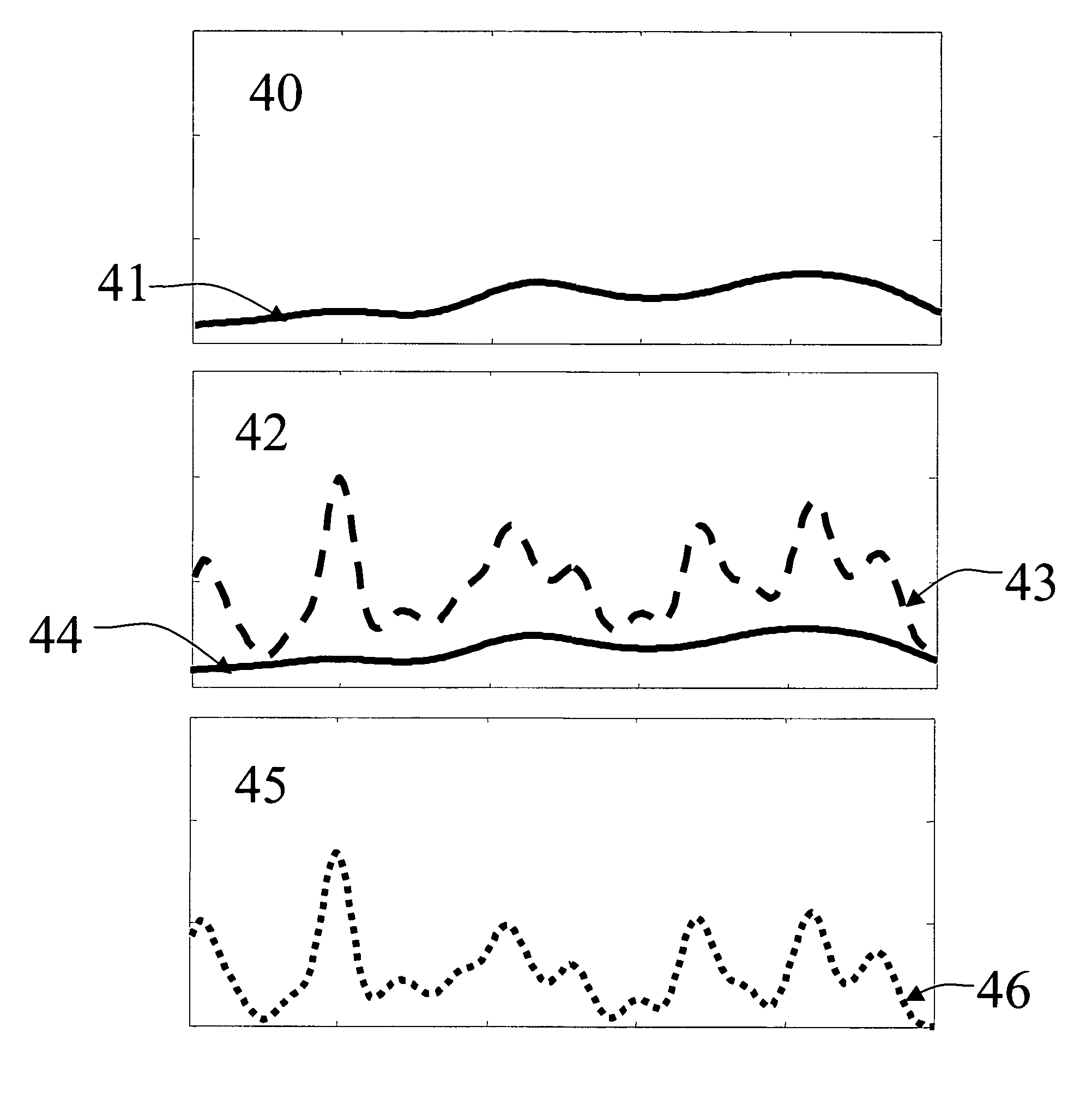
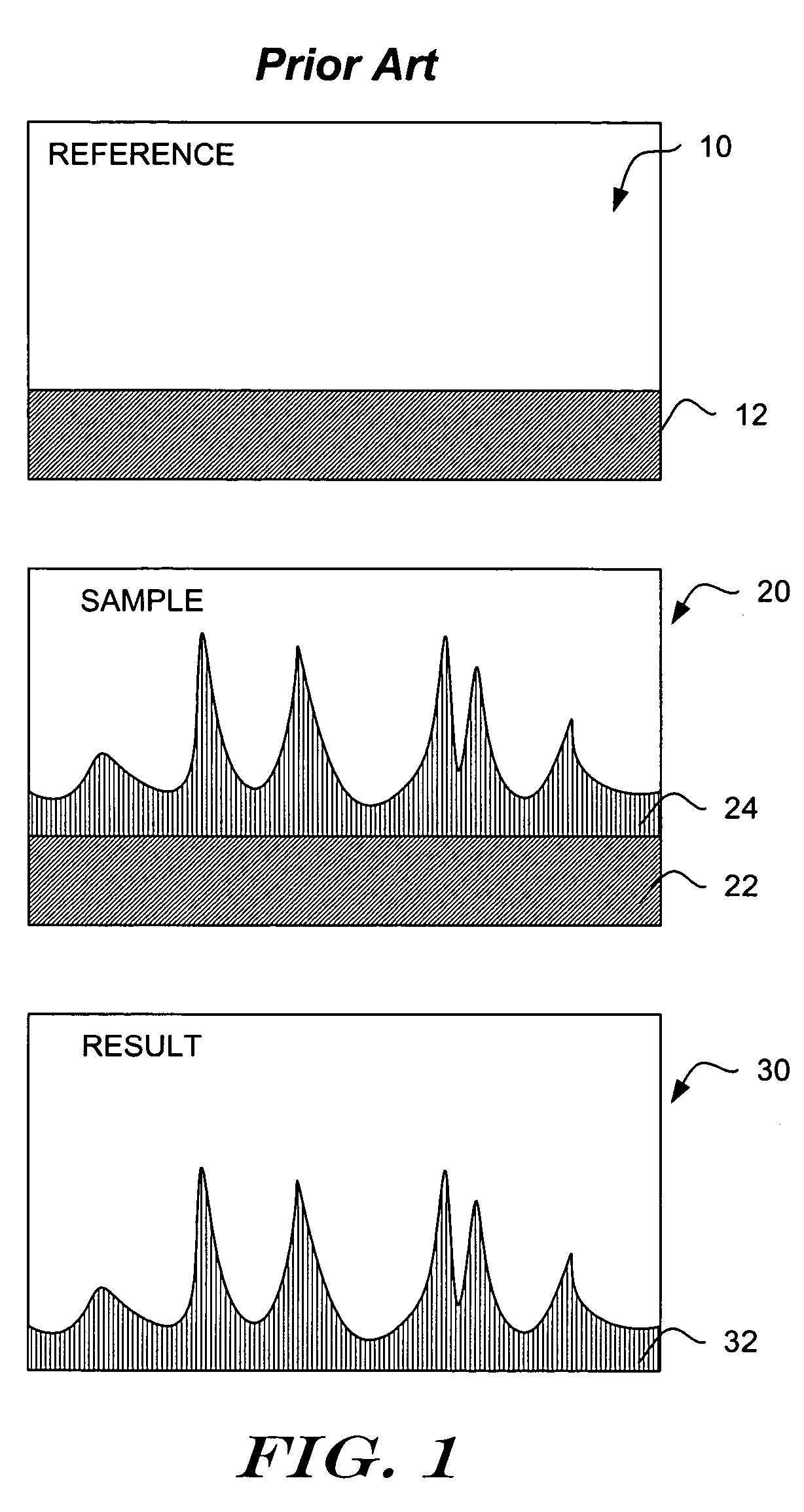
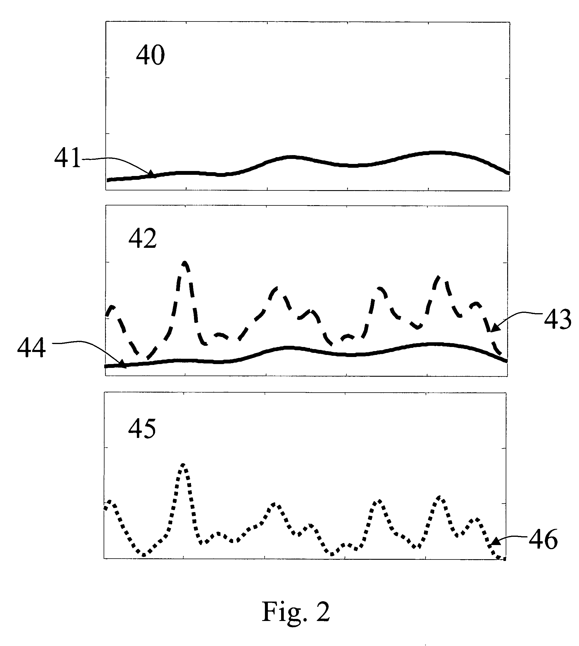
[0011]The present invention provides a method for adjusting measurements of samples for the measurement distortions such as those introduced by the state of a measurement device, or the environment of the sample or measurement device. Several measurements of a reference sample or samples can be analyzed for aspects or components of variation that are not related to variations in the reference sample or samples. These components of measurement variation are assumed to be related to distortions in the measurement. These distortion-related components of measurement variation can arise from known or unknown causes, and have known or unknown effects on the reference measurements or sample-measuring device measurements. The present invention can use the distortion-related reference component variations in conjunction with several sample measurements to approximate the distortions in the sample measurements, and, if desired, can compensate for the estimated distortions in the sample measurements.

Problems solved by technology

These distortion-related components of measurement variation can arise from known or unknown causes, and have known or unknown effects on the reference measurements or sample-measuring device measurements.
Current practice also is generally not applicable to situations where the reference sample varies in a manner that is not dependent on the environment or state of the instrument.

Method used


Image

  • Adaptive compensation for measurement distortions in spectroscopy
  • Adaptive compensation for measurement distortions in spectroscopy
  • Adaptive compensation for measurement distortions in spectroscopy

Examples


Embodiment Construction

[0022]The following detailed description should be read with reference to the drawings. The drawings depict illustrative embodiments and are not intended to limit the scope of the invention. While the following detailed description is written with reference to a spectroscopic measurement system for quantifying constituents in samples or classifying the samples into categories, the present invention has application to a range of data measurement systems. For example, the present invention can be used with respect to a sonic or magnetic resonance measurement or detection system. Also, the present invention can be used to determine characteristics other than the constitution of a sample, for example, to determine the speed of a moving object, the depth of a body of liquid, or the temperature of an object.

[0023]For the purposes of this disclosure, any range or combination of wavelengths of spectral or other data (including, for example, data captured using magnetic resonance, sonic, spa...


PUM

PropertyMeasurementUnit
concentrationaaaaaaaaaa
specific wavelengthaaaaaaaaaa
physical propertyaaaaaaaaaa

Abstract

Methods of reducing the effects of measurement device artifacts on a measurement of a sample are presented. A number of reference measurements performed with the measurement device are observed to identify reference independent components of the reference measurements. The variations of the reference independent components are used as surrogates for possible artifacts of the measurement device. A number of measurements of subjects similar to the sample are observed, and similarity components of the subject measurements that vary in a manner similar to the reference independent components may be identified. The sample measurement is then adjusted to remove at least part of the similarity components that correspond to the variations in the reference independent components. The adjustment of the sample measurement is thereby improved by reducing the effects of artifacts of the measurement device.

Description

FIELD OF THE INVENTION[0001]The present invention is related to methods for data capture and analysis. More specifically, the present invention is related to methods for the reduction of measurement errors, and is particularly useful in multivariate analysis of complex measurements such as those in human tissue.BACKGROUND OF THE INVENTION[0002]As new data collection technologies have evolved, allowing the analysis of more complex signals, techniques for analyzing such data have become more complex. For example, the introduction of new technologies in spectroscopy has allowed the collection of very large amounts of data. In some spectroscopic measurements, a high degree of sensitivity is needed to sense constituents that have relatively low concentrations or that lack highly selective spectral attributes. Devices used in such measurements, however, can capture extraneous signals, which can interfere with the accurate extraction of the desired information. For example, Johnson noise a...

Claims


Application Information

Patent Timeline
Patent Type & Authority Patents(United States)
IPC IPC(8): G01D18/00G01J3/28G01N21/27
CPCG01N21/274G01J3/28
Inventor BROWN, CHRISTOPHER D.
Owner INLIGHT SOLUTIONS
Learn More