Radio base station apparatus and radio communication method

a radio communication and base station technology, applied in the field of radio communication methods and radio base station apparatuses, can solve problems such as deterioration of communication quality, and achieve the effect of improving communication quality and satisfying communication quality

Inactive Publication Date: 2006-11-07
OPTIS WIRELESS TECH LLC
View PDF23 Cites 37 Cited by
  • Summary
  • Abstract
  • Description
  • Claims
  • Application Information

AI Technical Summary

Benefits of technology

[0007]An object of the present invention is to provide a radio base station apparatus and a radio communication method capable of carrying out radio communication with a satisfactory communication quality even when the fading correlation is small.
[0008]This object can be achieved by carrying out diversity transmission and reception without generating the directivity so that the distortion of the signal due to fading is compensated and the communication quality is improved even when the fading correlation of the respective received waves is small.

Problems solved by technology

Thus, since the direction of arrival (direction of angle . in FIG. 1) of the received radio wave can not be estimated correctly when the fading correlation is small, there exists a problem that desired directivity can not be correctly generated leading to deterioration of the communication quality.

Method used


Image

  • Radio base station apparatus and radio communication method
  • Radio base station apparatus and radio communication method
  • Radio base station apparatus and radio communication method

Examples


first embodiment

(First Embodiment)

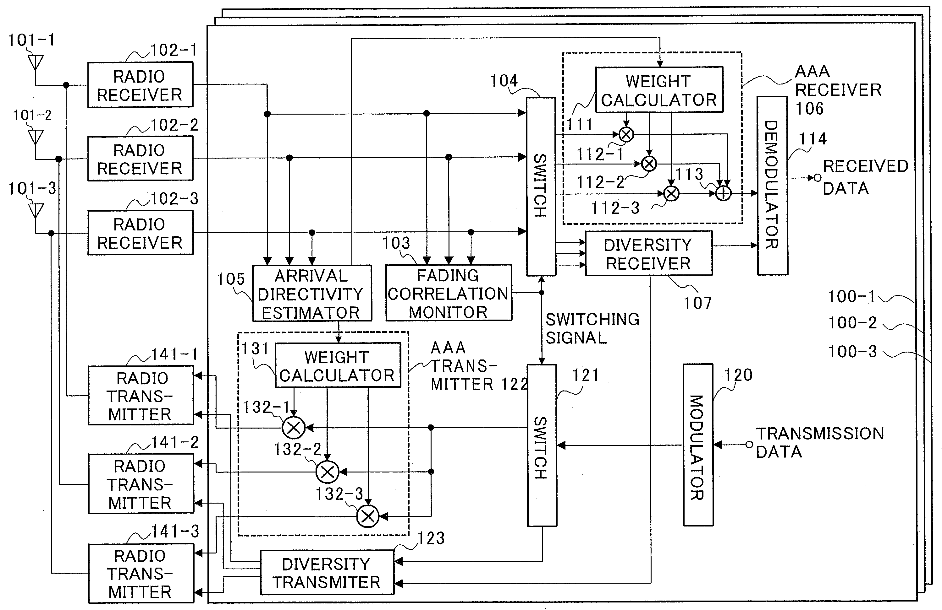
[0022]In a first embodiment, the case when the fading correlation is detected by monitoring the angle spread will be explained while directing the viewpoint to the fact that the larger the angle spread is the smaller fading correlation. That is to say, in order to carry out radio communication with a satisfactory communication quality, the base station apparatus according to the first embodiment estimates the angle spread based on the received signal, and when the estimated angle spread is smaller than a predetermined threshold value, it carries out the AAA transmission and reception to suppress the interference wave while carrying out diversity transmission and reception to compensate the deterioration of the signal when the angle spread is larger than a predetermined threshold value.

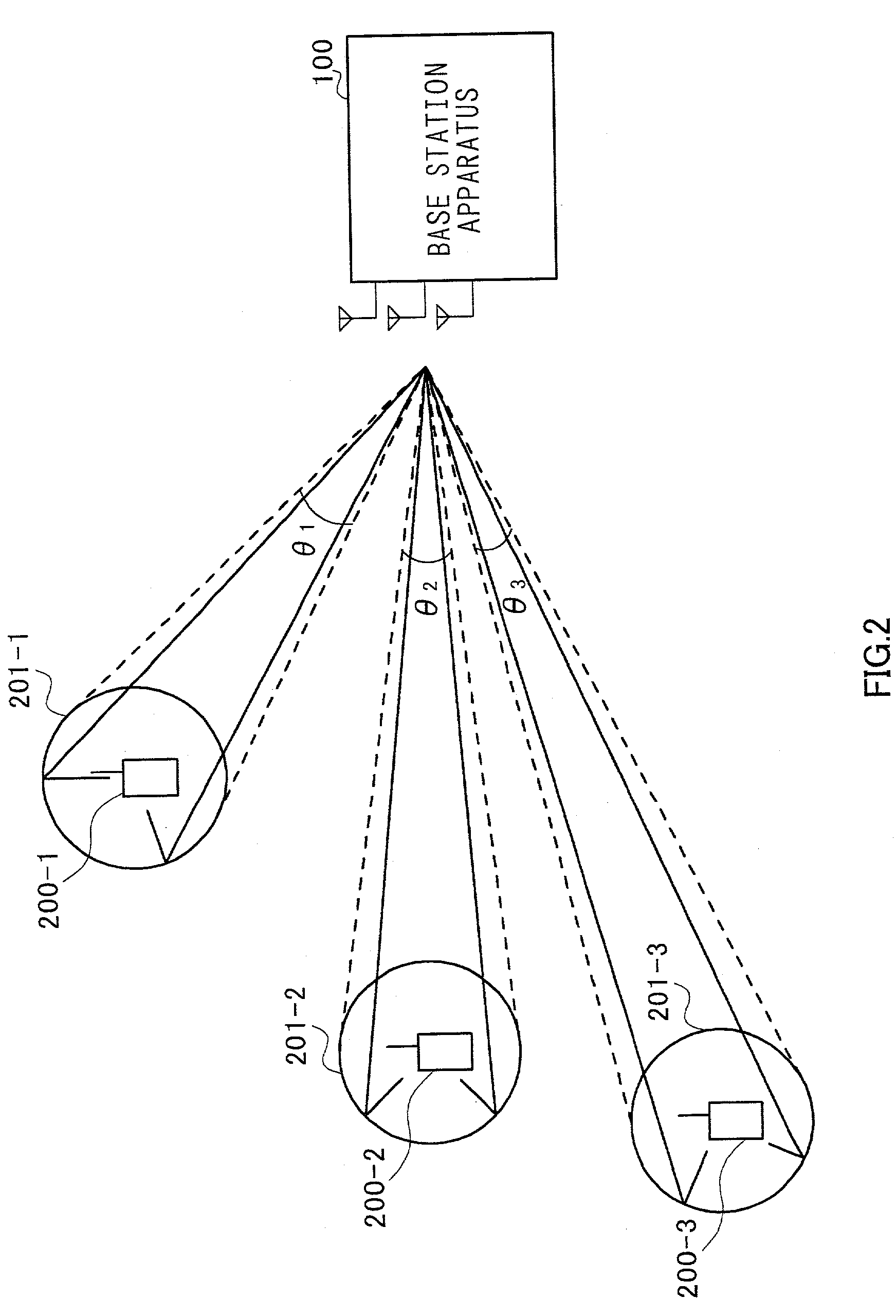
[0023]FIG. 2 is a diagram illustrating a base station apparatus according to the first embodiment of the present invention.

[0024]The radio wave transmitted from the radio base station...

second embodiment

(Second Embodiment)

[0055]The base station apparatus according to a second embodiment calculates a fading correlation value among the respective antenna elements, and when the calculated fading correlation value is larger than a predetermined threshold value, the interference wave is suppressed by carrying out the AAA transmission and reception while carrying out the diversity transmission and reception to compensate the distortion due to fading when the calculated fading correlation value is smaller than the threshold value, and hence, a radio communication with a satisfactory communication quality is carried out. That is to say, the second embodiment is different from the first embodiment in the point that the fading correlation among the respective antenna elements is monitored by calculating the fading correlation value itself.

[0056]FIG. 6 is a block diagram illustrating the configuration of a fading correlation monitor 103 according to the second embodiment of the present invent...

third embodiment

(Third Embodiment)

[0069]Examples in which the AAA transmission / reception and the diversity transmission / reception are switched over according to the distance between the base station apparatus and a communication terminal apparatus are given in third, fourth and fifth embodiments. That is to say, in the third embodiment, while taking into consideration the fact that the distance between the base station apparatus and the communication terminal apparatus can be estimated in accordance with the electric power of the received signal, the AAA transmission / reception and the diversity transmission / reception are switched over according to the received power. In the fourth embodiment, while taking into consideration the fact that the distance between the base station apparatus and communication terminal apparatus can be estimated according to the time lag (difference in timing) between the receiving timing of the received signal and the transmitting timing of the transmission signal, the AA...


PUM


Abstract

The fading correlation monitor 103 detects an angle spread of the communication terminal apparatus 200-1 and decides whether the angle spread has a larger or smaller relationship with a preset threshold value. When the estimated angle spread is smaller than the threshold value, the interference wave is suppressed by carrying out directive reception which is carried out by an AAA receiver 106 as well as performing directive transmission which is carried out in a transmitting circuit 122.While, when the estimated angle spread is larger than the predetermined value, the distortion of the signals due to the fading is compensated by carrying out diversity receiving which is carried out in a diversity receiver 107 as well as performing diversity transmission which is carried out in a diversity transmitter 123.On account of this, even when the fading correlation is small, it is possible to carry out a radio communication with a satisfactory communication quality.

Description

TECHNICAL FIELD[0001]The present invention relates to a radio base station apparatus and a radio communication method for directional transmission and reception.BACKGROUND ART[0002]In digital radio communication, adaptive array antenna (hereinafter, referred to as “AAA”) technology which adaptively controls the directivity of a plurality of antenna elements by adding weight to the antenna output is used. In the AAA technology, it is possible to suppress the interfering waves by adaptively controlling the directivity utilizing the fact that the directions of arrival of signals are different from each other. Accordingly, the AAA technology is preferred as a method for suppressing the interfering waves.[0003]Referring to FIG. 1, the formation of directivity pattern in a radio base station apparatus which utilizes the AAA technology will be described. FIG. 1 is a diagram showing a transmitted radio wave which is transmitted from a communication terminal apparatus arrives at a radio base...

Claims


Application Information

Patent Timeline
Patent Type & Authority Patents(United States)
IPC IPC(8): H04M1/00H01Q3/24G01S19/17G01S19/34G01S19/35H04B7/06H04B7/08H04B7/10H04B7/26H04W16/24H04W16/28H04W88/08
CPCH04B7/0615H04B7/0617H04B7/0689H04B17/309H04B7/086H04B7/0871H04W88/08H04B7/0619H04W16/24H04B7/0857
Inventor MIYOSHI, KENICHIUESUGI, MITSURU
Owner OPTIS WIRELESS TECH LLC
Why Eureka
Try Eureka