Cooling system for use in a portable communication device

a cooling system and portable communication technology, applied in the direction of machines/engines, mechanical equipment, positive displacement liquid engines, etc., can solve the problems of affecting the the fan noise generated by the cooling system may interfere with the user's conversation, and the modern portable communication device with mobile communication functions, such as cellular phones, personal digital assistants (pda) or the like, and achieves satisfactory communication quality of the portable communication device, reduces the operating temperature, and reduces the effect o

Active Publication Date: 2016-01-26
SUNONWEALTH ELECTRIC MACHINE IND
View PDF16 Cites 0 Cited by
  • Summary
  • Abstract
  • Description
  • Claims
  • Application Information

AI Technical Summary

Benefits of technology

[0007]It is therefore the objective of this invention to provide a cooling system for use in a portable communication device wherein the cooling system is capable of stopping the fan of the portable communication device or capable of controlling the fan to rotate in a slower speed when the portable communication device operates in a communication state with lower operational temperature. Thus, satisfactory communication quality of the portable communication device is maintained while the required cooling effect is provided for the portable communication device.

Problems solved by technology

Modern portable communication devices with mobile communication functions, such as cellular phones, Personal Digital Assistants (PDA) or the like, often overheat due to waste heat generated during the operation thereof.
This results in breakdown of the portable communication devices.
In this regard, the noise generated by the fan of the cooling system may interfere with the user's conversation.
The noise may disturb the ability of the user to hear clearly or even disturb the remote user on the call.
As a result, the call quality is affected.
In addition, a great deal of heat is generated when the portable communication device operates in a long duration of time.

Method used


Image

  • Cooling system for use in a portable communication device
  • Cooling system for use in a portable communication device
  • Cooling system for use in a portable communication device

Examples


Embodiment Construction

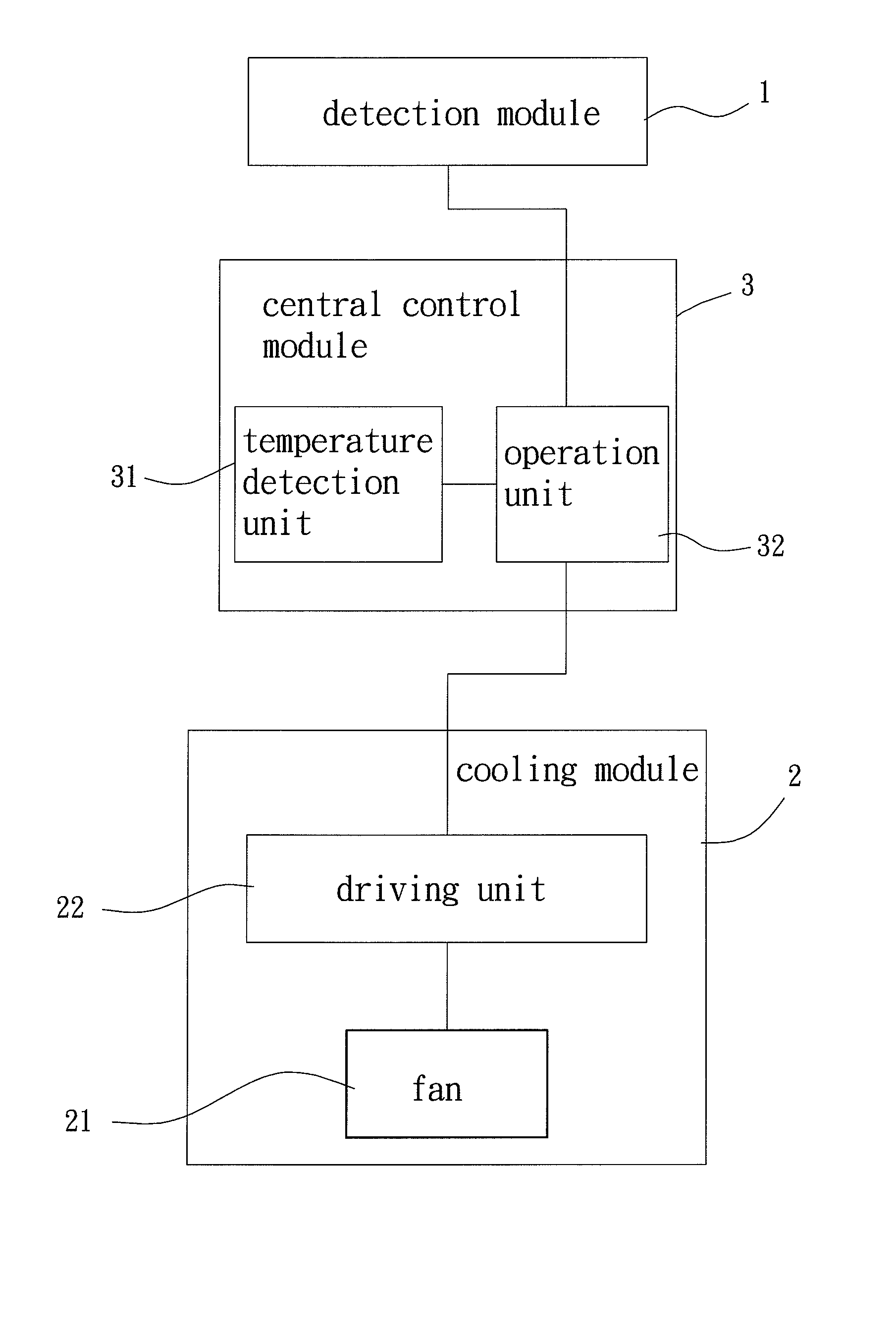
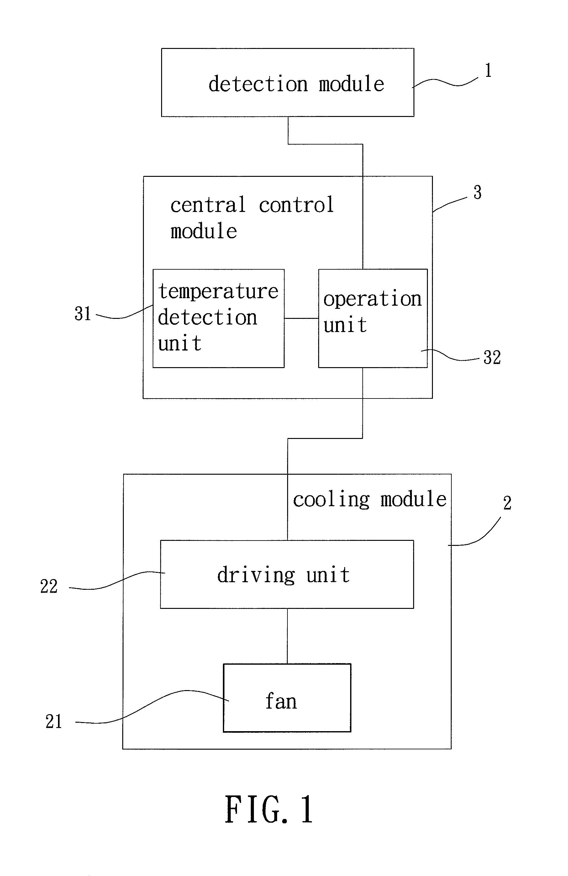
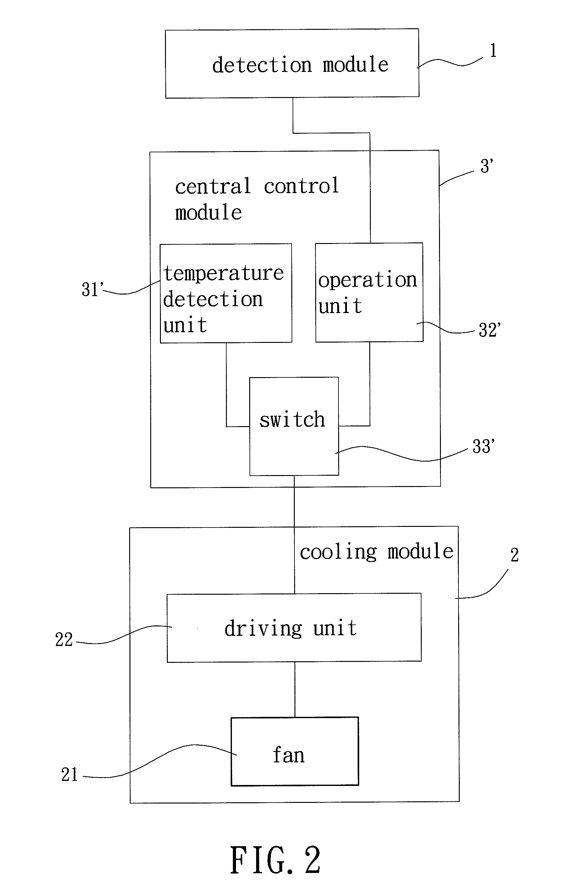
[0021]FIG. 1 shows a block diagram of a cooling system for use in a portable communication device according to a first embodiment of the invention. The cooling system includes a detection module 1, a cooling module 2 and a central control module 3. The detection module 1 is electrically coupled to the central control module 3. The cooling module 2 is electrically coupled to the central control module 3. The detection module 1 and the cooling module 2 may communicate with the central control module 3 through wired or wireless technology.

[0022]The detection module 1 detects whether a portable communication device, such as a cellular phone, a PDA, a tablet computer or the like, is in a communication state. When the detection module 1 detects that the portable communication device is in the communication state, the detection module 1 sends an acknowledgement signal to the central control module 3. When the detection module 1 detects that the portable communication device is not in the c...


PUM


Abstract

A cooling system for use in a portable communication device includes a detection module, a cooling module and a central control module. The detection module detects whether the portable communication device is in a communication state and generates an acknowledgement signal. The cooling module includes a fan and a driving unit. The central control module is electrically coupled to the detection module and the driving unit, detects an operational temperature of said device, and generates a detected temperature value corresponding to the detected operational temperature. The central control module controls the fan to operate in a silent mode or a cooling mode. The central control module controls the fan to operate in the silent mode if the central control module receives the acknowledgement signal when the detected temperature value is smaller than a temperature threshold value, else the central control module controls the fan to operate in the cooling mode.

Description

BACKGROUND OF THE INVENTION[0001]1. Field of the Invention[0002]The present invention generally relates to a cooling system for use in a portable communication device and, more particularly, to a cooling system that is installed in a portable communication device for expelling the heat from the interior of the portable communication device when the temperature of the portable communication device increases, ensuring the performance of the portable communication device.[0003]2. Description of the Related Art[0004]Modern portable communication devices with mobile communication functions, such as cellular phones, Personal Digital Assistants (PDA) or the like, often overheat due to waste heat generated during the operation thereof. This results in breakdown of the portable communication devices. To solve the problem, a cooling system is installed somewhere in the portable communication device where heat is generated, so as to prevent the portable communication device from overheating.[0...

Claims


Application Information

Patent Timeline
Patent Type & Authority Patents(United States)
IPC IPC(8): F04D15/00F04B19/20F04D27/00F01P5/04H05K7/20F04D25/08F04B49/06F04B49/20
CPCF04D15/0066F04B19/20F04B49/065F04D25/08F04D27/004F01P2005/046H05K7/20209Y02B30/70
Inventor HORNG, ALEX
Owner SUNONWEALTH ELECTRIC MACHINE IND
Why Eureka
Try Eureka