
Wireless communication system

a communication system and wireless technology, applied in the field of wireless communication systems, can solve the problems of limiting the flexibility of the layout of the apparatus, and achieve the effects of satisfactory communication quality, and convenient selection of informational signals

Active Publication Date: 2005-11-24
SONY CORP
View PDF9 Cites 0 Cited by
  • Summary
  • Abstract
  • Description
  • Claims
  • Application Information

AI Technical Summary

Benefits of technology

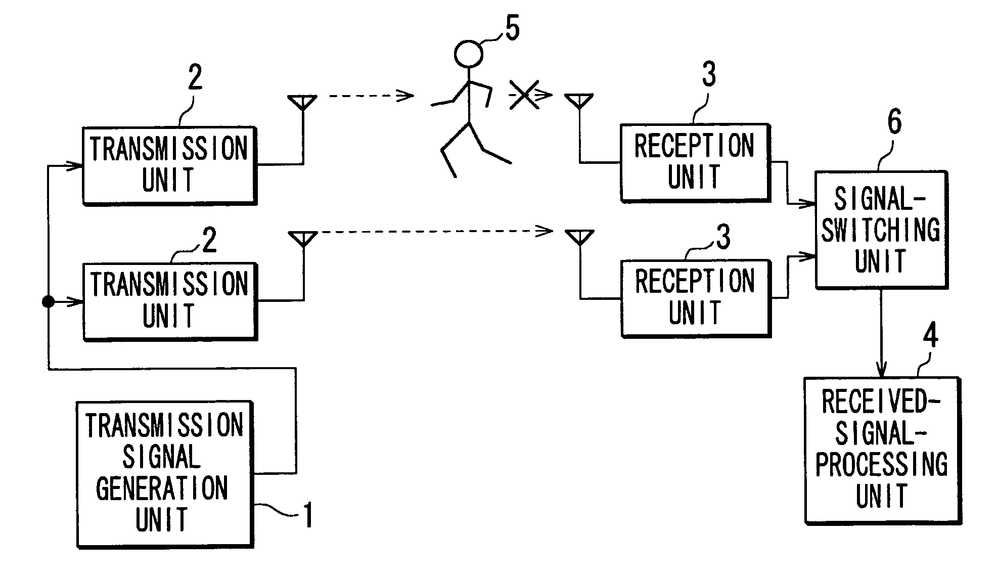
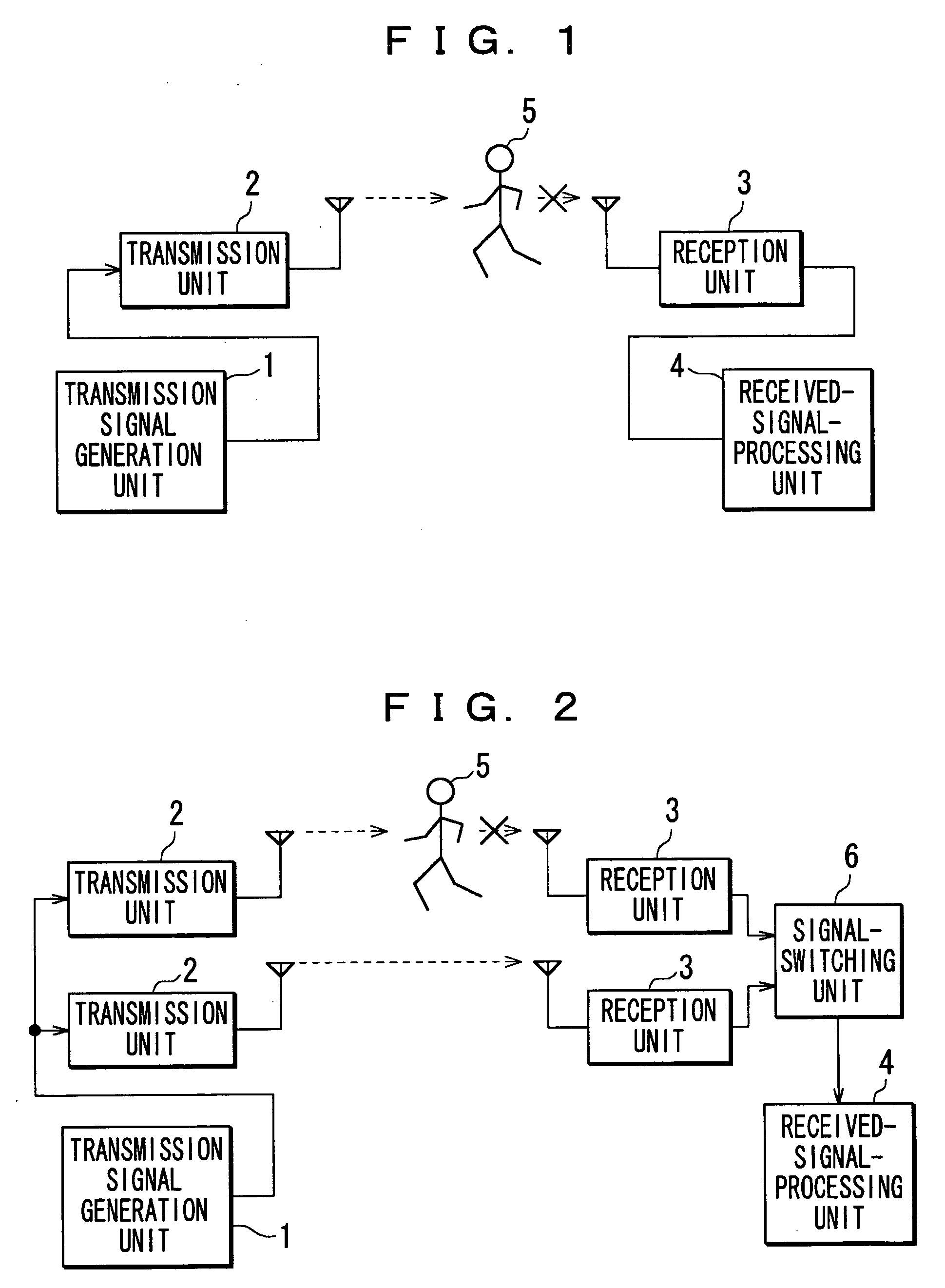
The patent describes a wireless communication system that can receive multiple signals from different paths and select the best signal based on communication quality. This is important because the length of the paths between the signals can vary, causing delays or blocking. The system uses a synchronization signal to ensure that all the signals are synchronized, and a time difference between the signals is minimized. This allows for proper signal processing and improved communication quality. The system also includes multiple reception devices that detect the synchronization signal and store the informational signal based on the detected synchronization signal. This ensures that the signals are synchronized with each other and can be selected based on their quality. Overall, the system provides better wireless communication by selecting the best signal from multiple paths.

Problems solved by technology

However, when the image display apparatus and the image signal output apparatus are separately provided, it may be required to connect those apparatuses to each other using a cable, thereby limiting flexibility of a layout for the apparatuses.

Method used


Image

  • Wireless communication system
  • Wireless communication system
  • Wireless communication system

Examples


Embodiment Construction

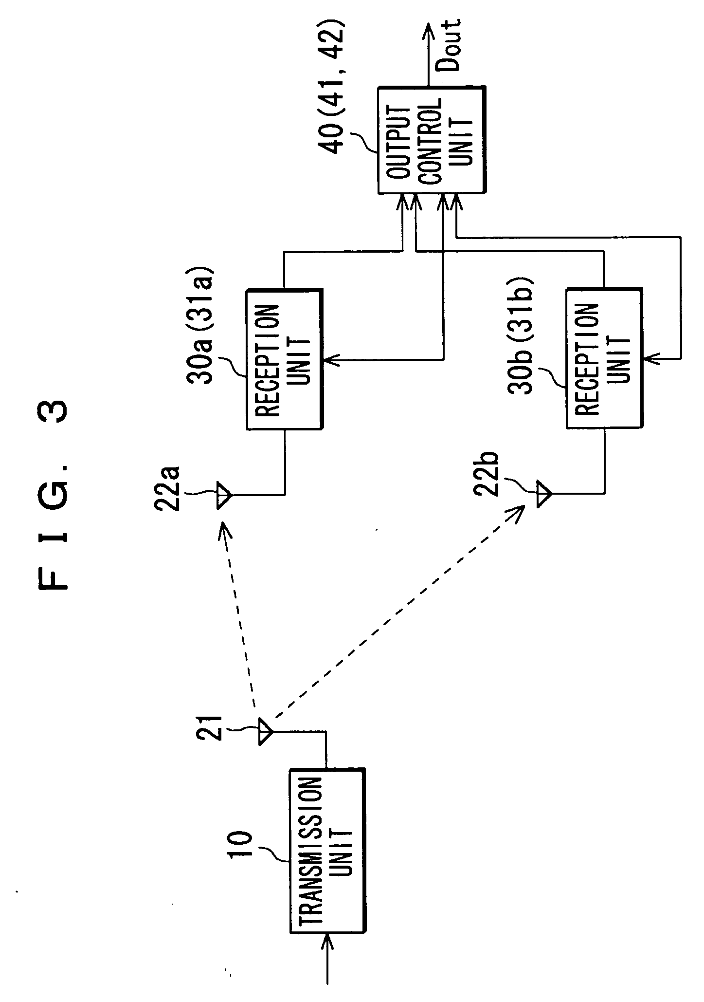
[0037] Referring now to the drawings, preferred embodiments of the invention will be described specifically below. FIG. 3 shows a configuration of an embodiment of a wireless communication system according to the invention according to path diversity.

[0038] This embodiment of a wireless communication system is used when an antenna of a transmission apparatus has wide beam width. For example, an antenna 22a connected with a reception unit 30a (31a) of reception apparatus and an antenna 22b connected with a reception unit 30b (31b) of reception apparatus receive a wireless signal transmitted from an antenna 21 connected with a transmission unit 10. An output control unit 40 (41, 42) compares communication quality in the reception unit 30a when receiving the wireless signal with communication quality in the reception unit 30b when receiving the wireless signal. The output control unit 40 (41, 42) then determines which one of the communication qualities is satisfactory and outputs only...


PUM


Abstract

A wireless communication system has transmission apparatus transmitting a wireless signal based on a transmission unit and reception apparatus. The reception apparatus includes plural reception devices receiving the wireless signal to obtain the informational signals and output-controlling device selecting any informational signal from the informational signals. The reception device has communication-quality-detecting device that detects communication quality of the wireless signal, a memory storing the informational signal, and synchronization-detection-storage-controlling device that detects the synchronization signal and controls the memory to store the informational signal based on a detected result of the synchronization signal. The output-controlling device reads the informational signals out of the memories with the signals being synchronized after the reception devices have detected the synchronization signals, selects the reception device having satisfactory communication quality based on a detected result of the communication quality, and outputs the informational signal read out of the selected reception device.

Description

CROSSREFERENCE TO RELATED APPLICATION [0001] The present invention contains subject matter related to Japanese Patent Application JP 2004-149635 filed in the Japanese Patent Office on May 19, 2004, the entire contents of which being incorporated herein by reference. BACKGROUND OF THE INVENTION [0002] 1. Field of the Invention [0003] The present invention relates to a wireless communication system. More particularly, it relates to a wireless communication system for an image display system in which a wireless signal is transmitted and plural receivers can receive the wireless signal. [0004] 2. Description of Related Art [0005] An image display system has recently realized increase in the flexibility in a system configuration by separating an image display mechanism. For example, various kinds of image display apparatuses each constituted of a display element such as a plasma display panel and a liquid crystal panel and image signal output apparatus having a tuner function, a recordin...

Claims


Application Information

Patent Timeline
Patent Type & Authority Applications(United States)
IPC IPC(8): H04B7/26H04B7/04H04B7/06H04B7/08H04L1/02
CPCH04B7/0613H04B7/082H04B7/0811H04B1/40H04B7/08
Inventor SUGITA, TAKEHIRO
Owner SONY CORP
Learn More