Base station device, mobile terminal device, wireless communication system, and wireless communication method

a mobile terminal and wireless communication technology, applied in the field of base station devices, mobile terminal devices, wireless communication systems, wireless communication methods, can solve the problems of insufficient performance, scheme selection of optimal subcarriers for communication, and relative low transmission power amplifying performance, etc., to achieve excellent communication efficiency and excellent papr characteristics

Active Publication Date: 2013-04-02
SHARP KK
View PDF10 Cites 0 Cited by
  • Summary
  • Abstract
  • Description
  • Claims
  • Application Information

AI Technical Summary

Benefits of technology

[0025]According to the wireless communication system, the wireless transmission device, the wireless communication method, and the program of the present invention, the number of frequency domain signals included in each segment is set to a value satisfying a predetermined communication quality, based on channel conditions of subcarriers to which the frequency domain signals are allocated. For this reason, predetermined communication quality and excellent communication efficiency can be achieved. Further, excellent PAPR characteristics can be achieved while the number of frequency domain signals included in each segment is set to be as large as possible.

Problems solved by technology

However, the high peak power is a fatal problem for uplink communication (from the mobile station to the base station device) achieving a relatively-low transmission-power amplifying performance.
However, both allocation schemes cannot achieve selection of optimal subcarriers for communication.
Sufficient performance cannot be achieved especially in a channel environment causing high frequency selectivity or in an environment affected by many interference signals from other cells.

Method used


Image

  • Base station device, mobile terminal device, wireless communication system, and wireless communication method
  • Base station device, mobile terminal device, wireless communication system, and wireless communication method
  • Base station device, mobile terminal device, wireless communication system, and wireless communication method

Examples


first embodiment

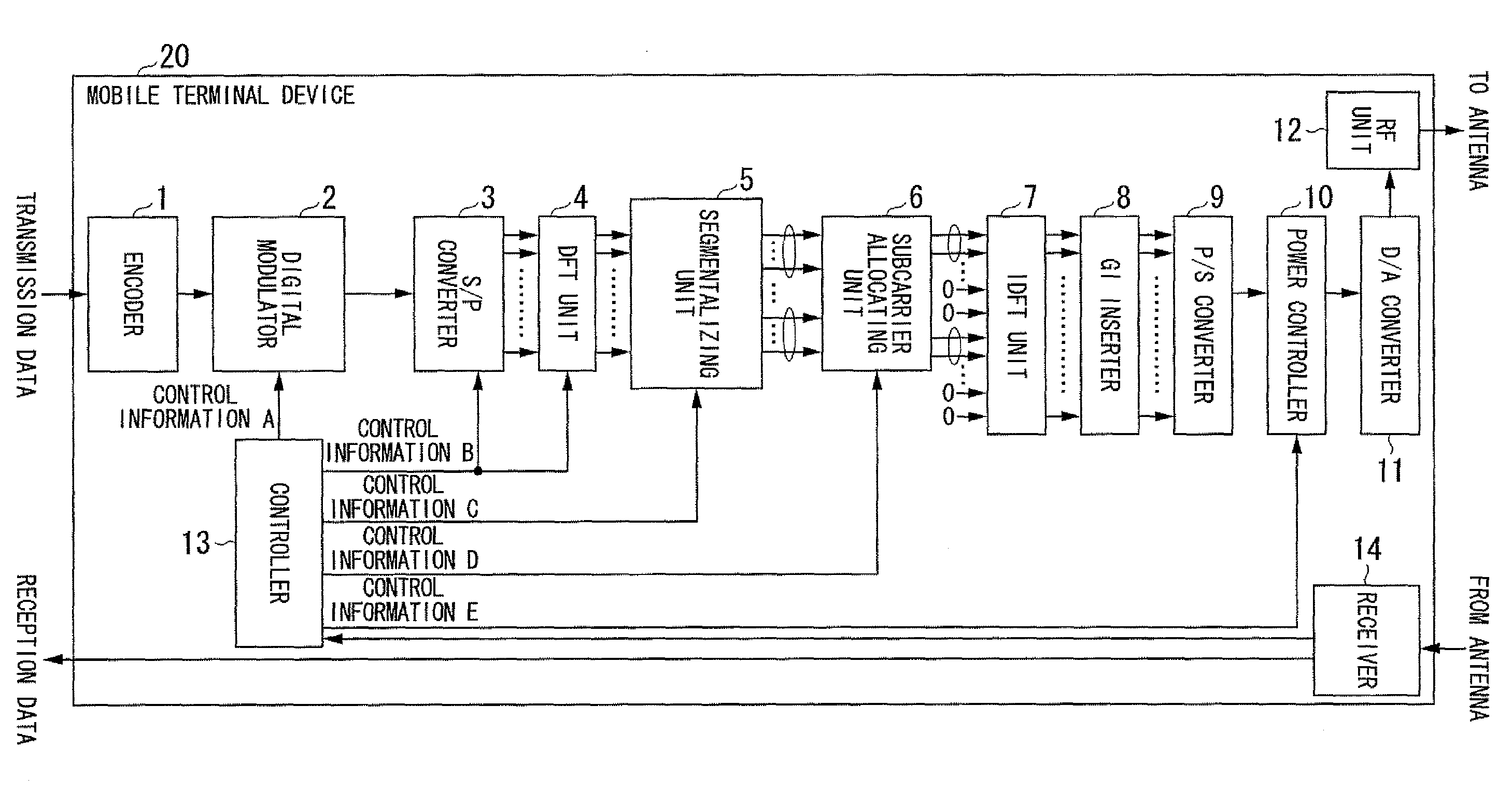
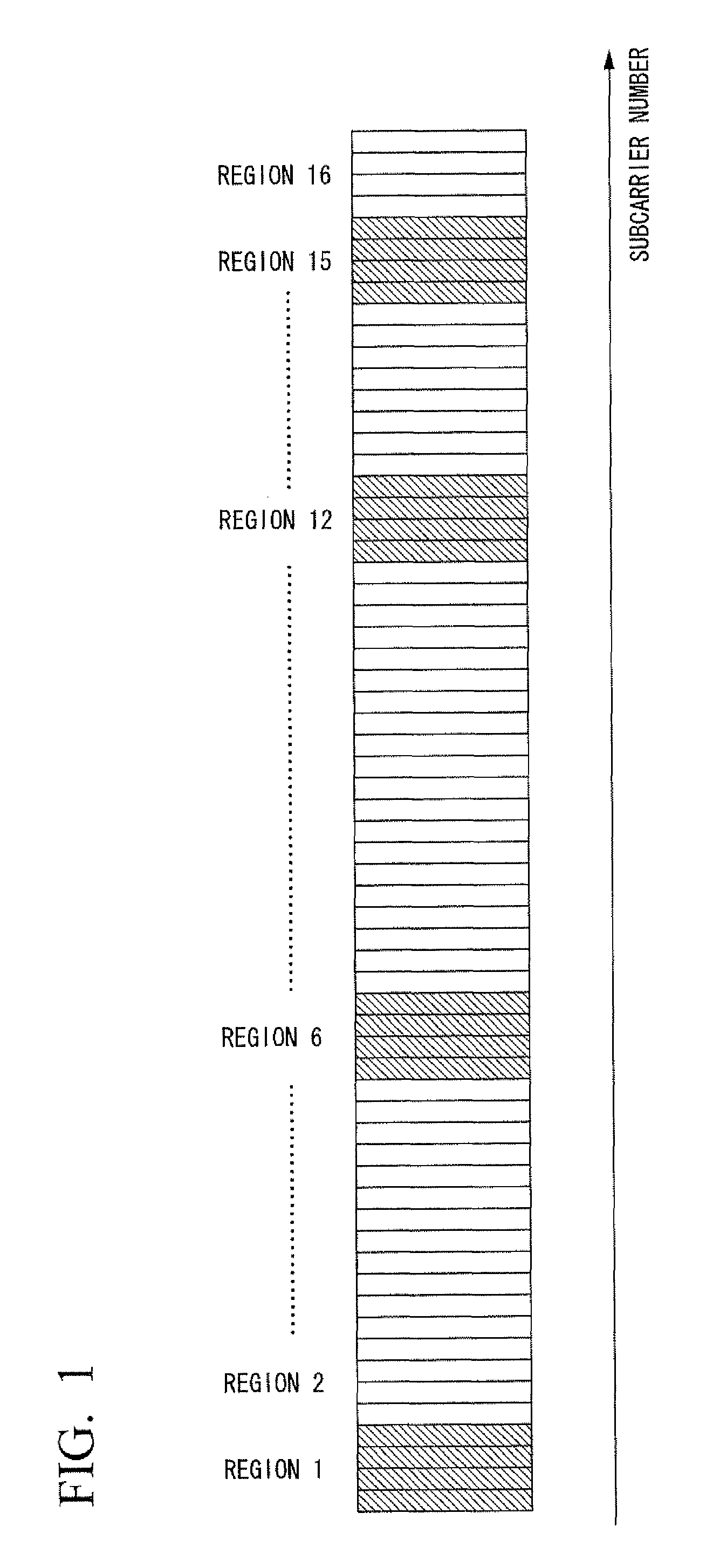
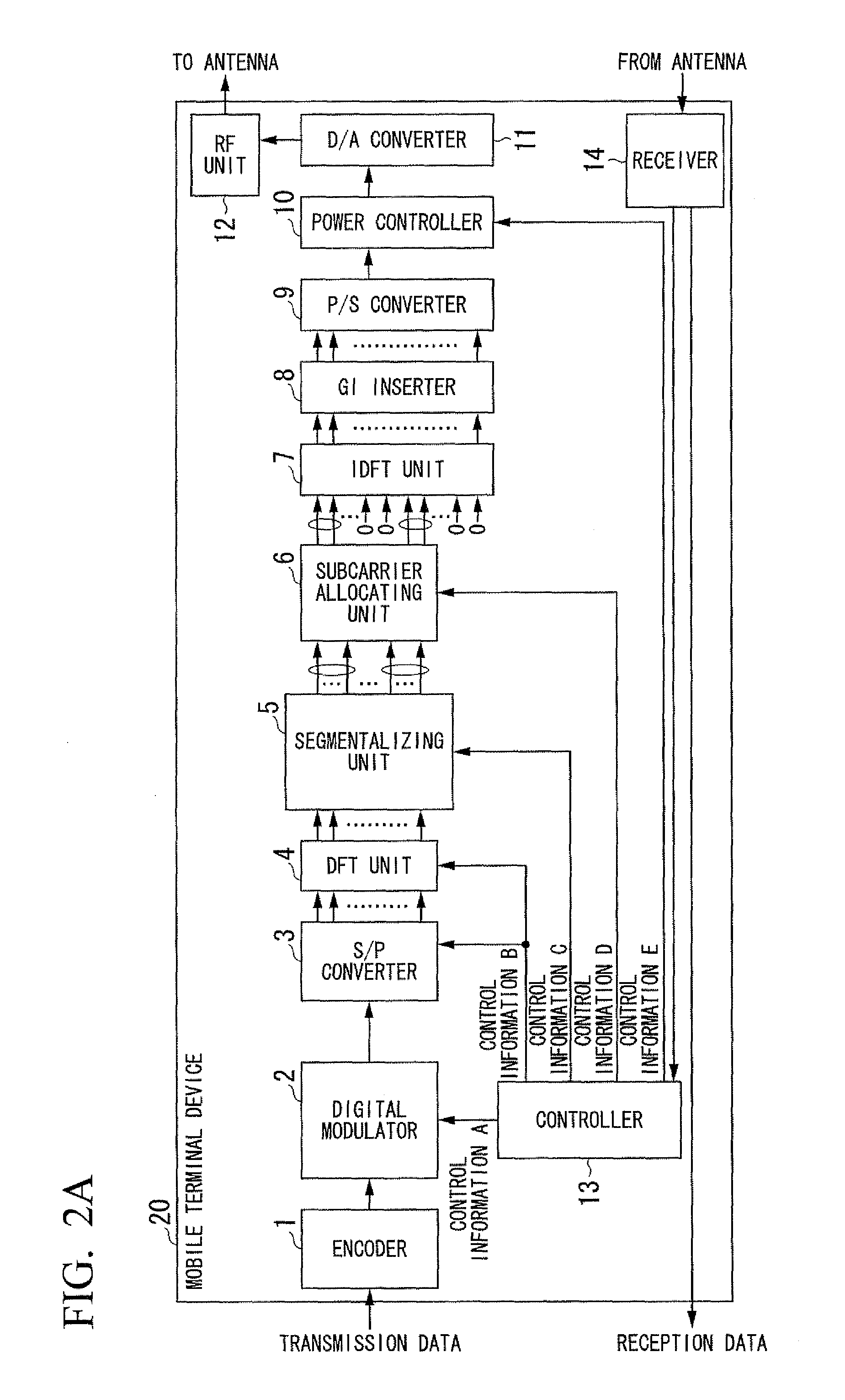
[0052]A first embodiment explains the adaptive control achieved by changing the number of frequency domain signals included in each segment. For simplification of explanation, it is assumed that the control information A indicates one of BPSK and QPSK, and the control information B indicates 32 subcarriers that do not change (the total number of subcarriers to be used is 64). Additionally, the control information D, i.e., subcarrier allocation is suitably selected based on the number of frequency domain signals included in each segment, as will be explained later. It is assumed in the first embodiment that the base station device 30, which is the transmission destination of the mobile station device 20, informs the mobile station device 20 of an SINR of each subcarrier. Although it is explained here that the controller 13 of the mobile station device 20 determines subcarriers to be used, the base station device 30 may determine subcarriers to be used and inform the mobile station de...

second embodiment

[0067]A mobile terminal device and a base station device that are used in a second embodiment are the same as ones explained in the first embodiment with reference to FIGS. 2A and 2B except for the following. In other words, the control information pieces C and D, which are output from the controller of the mobile terminal device, differ. Consequently, the configuration of the controller 13 is changed with this respect. The same can apply to the base station device. This situation is explained here. The second embodiment explains a different method from that of the first embodiment where parameters shown in Table 1 are selected. Therefore, the total number of subcarriers to be used can be selected from 64 (full), 32 (half), and 16 (quarter). A first modulation scheme can be selected from 16QAM, QPSK, and BPSK. The number of frequency domain signals included in each segment can be selected from the types shown in Table 1, i.e., from LS-1, LS-8, LS-16, LS-32, and LS-64. An isolated ce...

third embodiment

[0076]A mobile terminal device and a base station device that are used in a third embodiment are the same as those explained in the first embodiment with reference to FIGS. 2A and 2B except for the following. In other words, the control information pieces C and D, which are output from the controller of the mobile terminal device, differ. Consequently, the configuration of the controller 13 is changed in this respect. The same can apply to the base station device. This situation is explained here. The third embodiment explains a case where DFT-s-OFDM, in which adaptive control is performed, is used for a single frequency reuse cellular system. The single frequency reuse cellular system is a system in which the same frequency band is used by every cell, and therefore high frequency utilization efficiency can be achieved, but the effects of interference signals from neighboring cells are problematic. In other words, interferences are primary factors of SINRs in the system.

[0077]To exp...


PUM


Abstract

A wireless transmission device converts signals having been subjected to a first modulation into frequency domain signals, and allocates the frequency domain signals converted to subcarriers for transmission. The wireless transmission device includes: a controller that selects, based on channel qualities of the subcarriers to which the frequency domain signals are allocated, a value satisfying a predetermined communication quality as control information indicative of the number of frequency domain signals included in each of segments into which the frequency domain signals are segmentalized; and an allocating unit that segmentalizes the frequency domain signals into segments, each of the segments including the same number of frequency domain signals as the value selected as the control information by the controller, and allocates the frequency domain signals included in each of the segments to sequential subcarriers.

Description

TECHNICAL FIELD[0001]The present invention relates to a base station device, a mobile terminal device, a wireless communication system, and a wireless communication method. Particularly, the present invention relates to a base station device, a mobile terminal device, a wireless communication system, and a wireless communication method, using spectrum control single carrier communication in which one or more frequency domain signals can be allocated to multiple sub carriers.[0002]Priority is claimed on Japanese Patent Application No. 2007-304321, filed Nov. 26, 2007, the content of which is incorporated herein by reference.BACKGROUND ART[0003]Recently, next generation mobile communication systems have been extensively studied. As a method of enhancing the system frequency utilization efficiency, a single frequency reuse cellular system, in which each cell uses the same frequency band, has been proposed.[0004]OFDMA (Orthogonal Frequency Division Multiple Access) is dominant in a down...

Claims


Application Information

Patent Timeline
Patent Type & Authority Patents(United States)
IPC IPC(8): H04K1/10
CPCH04L5/0007H04L5/0039H04L5/0044H04L5/006H04L5/0041H04W72/0453
Inventor HAMAGUCHI, YASUHIRONAMBA, HIDEOTO, SHIMPEIYOKOMAKURA, KAZUNARI
Owner SHARP KK
Why Eureka
Try Eureka