Boat hull

a technology for boats and hulls, applied in the field of boat hulls, can solve the problems of affecting the safety of passengers, and capsize the boat, and achieve the effects of reducing friction, maximizing speed and handling characteristics, and effectively capturing large volumes of air

Active Publication Date: 2019-12-31
KYLE JAMES H +1
View PDF48 Cites 7 Cited by
  • Summary
  • Abstract
  • Description
  • Claims
  • Application Information

AI Technical Summary

Benefits of technology

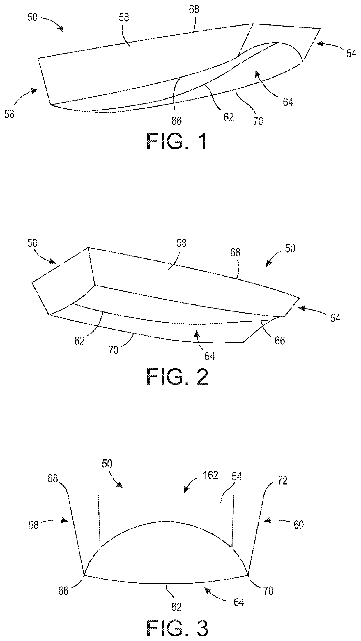
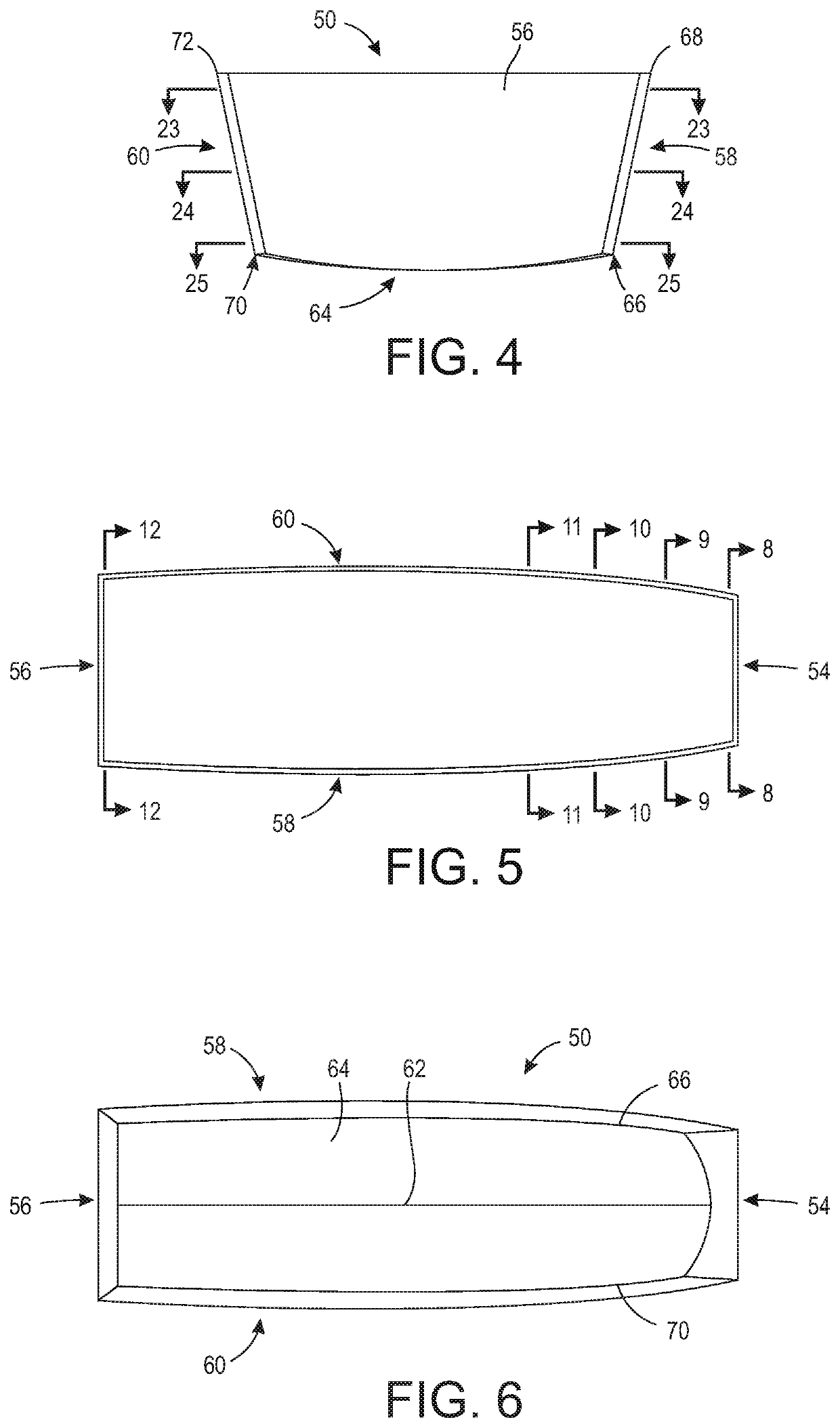
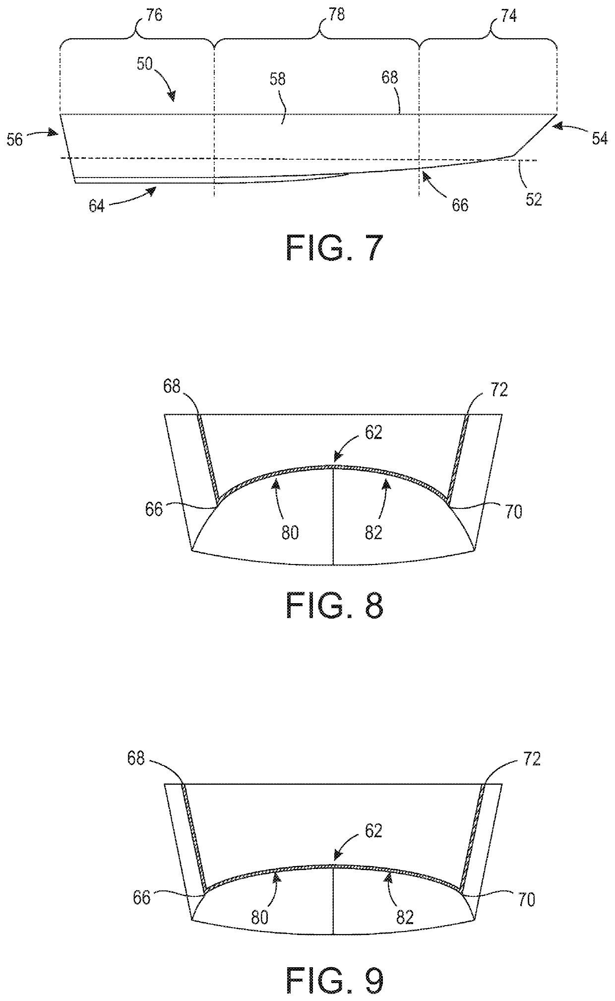
[0010]The present invention broadly comprises a hybrid hull form for mono-hull planing vessels which provides optimal speed and handling characteristics. In various embodiments, the hull form comprises the combined features of an inverted V or concave hull forward and a convex or V section hull aft, with the areas inboard of a continuous chine being generally concave and highly shaped to guide and divert water and energy trapped in the concave forward sections down, aft, and gradually outboard to exit either side of the centerline, i.e., away from the propellers. The generally rectangular deck plan shape, combined with the concave forward sections, create the required cavity under the hull to effectively trap large volumes of air and water which lifts the hull at speed while reducing friction. The trapped aerated water is less dense than solid water which cushions the ride in rough conditions.

Problems solved by technology

For example, long parallel chines act like runners on a sled thereby making turning the boat extremely difficult.
The foregoing is unsettling to the crew, and a higher center of gravity of the hull structure combined with the centrifugal force generated during the turn can capsize the boat.
The lack of heel in a turn combined with the near vertical and straight fore and aft sides of a boat using this hull can cause a condition known as “tripping over the chine”, where during a sliding turn, the edge of the hull strikes a wave, the chine catches on the water and the boat trips over the chine, rapidly tipping or flipping the boat athwartships.
Furthermore, the inverted V section greatly reduces the depth of the hull along the centerline of the boat amidships and forward thereby reducing the useable internal volume of the boat and raising the center of gravity of the hull.
During this transitional speed, i.e., the changing between displacement and planing modes where the boat has to “climb” over its own bow wave, the boat is less stable, hard to steer, and forward visibility is often dangerously reduced.
Another unfavorable characteristic is the tendency to generate a large bow wave which, when piercing oncoming waves and water, causes this wave to fly outboard and upward, and potentially landing on the boat.
Still yet another problem is the direct relationship between ride quality and required horsepower, i.e., deeper sections and greater deadrise result in a softer ride but greatly increase the horsepower requirements.
Yet another issue is the reduced stability of the boat while operating below planing speeds.
Conventional hulls with moderate deadrise are unstable when beached and make approaching the shore difficult due to their deeper draft.
They typically are very fast requiring less energy to power them; however, they are harder to steer, lack useable internal volume, can pound in a seaway, and often are more complicated to construct.
For example, the increased form drag caused by the added drag of the tri-hulls' sponsons, in addition to its increased hull mass due to added surface area, requires more power to propel the craft.
For example, known V hull designs are incapable of using trapped air and contained bow waves to reduce slamming while also increasing efficiency.
In fact, some hull designs force air towards the center of the hull, inwardly toward the propeller, thereby causing cavitation and steering issues.

Method used


Image

  • Boat hull
  • Boat hull
  • Boat hull

Examples


Embodiment Construction

[0060]At the outset, it should be appreciated that like drawing numbers on different drawing views identify identical, or functionally similar, structural elements of the invention. While the present invention is described with respect to what is presently considered to be the preferred aspects, it is to be understood that the invention as claimed is not limited to the disclosed aspects.

[0061]Furthermore, it is understood that this invention is not limited to the particular methodologies, materials and modifications described and as such may, of course, vary. It is also understood that the terminology used herein is for the purpose of describing particular aspects only, and is not intended to limit the scope of the present invention, which is limited only by the appended claims.

[0062]Unless defined otherwise, all technical and scientific terms used herein have the same meaning as commonly understood to one of ordinary skill in the art to which this invention belongs. Moreover, as us...


PUM


Abstract

A boat hull having a design water line, the boat hull including a bow, a stern, a starboard side having a starboard chine and a starboard gunwale, a port side having a port chine and a port gunwale, a hull center line, and a bottom surface formed between the bow, the stern, the starboard chine and the port chine. The bottom surface includes first, second and third portions. The first portion is proximate the bow and includes a first concave surface and a second concave surface, the first concave surface projects from the hull center line towards the starboard chine and the second concave surface projects from the hull center line towards the port chine. The second portion is proximate the stern and includes a first convex surface and a second convex surface.

Description

FIELD OF THE INVENTION[0001]The invention broadly relates to boat hulls, more specifically to boat hulls designed to minimize the formation of a wake, and even more particularly to a boat hull designed to minimize the formation of a wake while also minimizing cavitation. The present boat hull is an improved hybrid hull form for mono-hull planing vessels having characteristics of both inverted V bottom and conventional V bottom hull forms.BACKGROUND OF THE INVENTION[0002]The inverted V bottom hull form, commonly known as a sea sled, was invented by Albert Hickman. The original hull form consisted of a rectangular hull platform with an inverted V section at the bow, with the V section becoming continuously and progressively shallower toward the stern until disappearing or nearly disappearing at the transom. The Hickman hull form has been recognized as one of the most efficient non-stepped planing hull forms having the ability to carry as much as eighty pounds per horsepower at planing...

Claims


Application Information

Patent Timeline
Patent Type & Authority Patents(United States)
IPC IPC(8): B63B1/20B63B1/08B63B1/06B63B1/04
CPCB63B1/08B63B1/042B63B1/20B63B1/06B63B2001/201Y02T70/10
Inventor KYLE, JAMES H.HIX, LISA C.
Owner KYLE JAMES H
Why Eureka
Try Eureka