
Image processing device and image processing method

a technology of image processing and image processing device, which is applied in the field of image processing device and image processing method, can solve the problems of extremely small degree of effect of original image, inability to correctly obtain the large degree of effect of haze, etc., to achieve the effect of removing haze without losing the detail of a high-luminance subj

Active Publication Date: 2019-12-31
FUJIFILM CORP
View PDF13 Cites 0 Cited by
  • Summary
  • Abstract
  • Description
  • Claims
  • Application Information

AI Technical Summary

Benefits of technology

[0010]The present invention has been made in consideration of the above-mentioned situations, and its object is to provide an image processing device and an image processing method capable of removing haze (reducing the effect of haze) without losing detail of a high-luminance subject.
[0012]According to this aspect, for each pixel of which the effect estimation value for estimating the degree of effect of the removal image on the input image indicates a value in the range from the boundary value to the second limit value, it is determined that the degree of effect of the removal image is not correctly estimated on the basis of the high-luminance subject which is not the removal image, and thus the amount of correction is suppressed. Therefore, it is possible to prevent loss of detail of a high-luminance subject.
[0027]According to this aspect, for each pixel of which the effect estimation value for estimating the degree of effect of the removal image on the input image indicates a value in the range from the boundary value to the second limit value, it is determined that the degree of effect of the removal image is not correctly estimated on the basis of the high-luminance subject which is not the removal image, and thus the amount of correction is suppressed. Therefore, it is possible to prevent loss of detail of a high-luminance subject.
[0028]According to the present invention, it is possible to remove haze without losing detail of a high-luminance subject.

Problems solved by technology

In this case, as can be seen from the above description, in the high-luminance image range, processing is performed such that the degree of effect of haze on the original image is not correctly obtained, and the degree of effect of haze is extremely large regardless of the actual degree of effect, and the degree of effect of the original image is extremely small.
At that time, in a case where haze is intended to be removed, there was a problem that the high-luminance image range is saturated in the corrected image, and the detail (fine change of luminance and color) thereof is lost.

Method used


Image

  • Image processing device and image processing method
  • Image processing device and image processing method
  • Image processing device and image processing method

Examples


first embodiment

[0098]FIG. 6 is a graph illustrating the correspondence relationship between the dark channel value D and the transmittance tin the

[0099]In the drawing, the maximum value Dmax indicates a maximum value of the dark channel values D(x) of all the pixels in the input image I, and the dark channel value D indicates a value in the range of 0 or more and Dmax or less.

[0100]In a case where there is a subject having a higher luminance than that of haze, the dark channel value D may be greater than 1. At this time, the maximum value Dmax also has a value greater than 1.

[0101]On the other hand, the transmittance t is a value in the range of 0 or more and 1 or less.

[0102]Then, at a value in the range where the dark channel value D is equal to or greater than 0 and equal to or less than 1 (the range from 0 to 1), the dark channel value D and the transmittance t have the relationship of Expression (9), that is, the relationship of the straight line L1 in FIG. 6. Therefore, the transmittance t is...

second embodiment

[0125]FIG. 8 is a graph illustrating the correspondence relationship between the dark channel value D and the transmittance tin the

[0126]In the transmittance calculation processing, the correction processing means 18 is able to use the relationship of FIG. 8 instead of FIG. 6.

[0127]As shown in the drawing, in a case where the dark channel value D is a value in the range of 0 or more and 1 or less, the transmittance t is acquired by the relationship of Expression (12), that is, the relationship of the curve L3 in FIG. 8.

t=1−Dr1   (12)

[0128]Here, r1 is set to be less than 1.

[0129]In contrast, in a case where the dark channel value D is a value in the range of greater than 1, the transmittance t is acquired by the relationship of Expression (13), that is, the curve L4 in FIG. 8.

t={(D−1) / (Dmax−1)}r2   (13)

[0130]Here, r2 is set to be greater than 1.

[0131]Here, in Expressions (12) and (13), it is desirable that r1 is a value less than 1 and r2 is a value of greater than 1, but r1 may be a...

third embodiment

[0134]FIG. 9 is a graph illustrating the correspondence relationship between the dark channel value D and the transmittance t in the

[0135]Here, the dark channel value D in the present embodiment is different from those in the first and second embodiments, and it does not correspond to the dark channel value in its original sense, but is referred to as a dark channel value in the present embodiment.

[0136]In the present embodiment, the dark channel value calculation means 16 calculates the dark channel value D(x) of the pixel x for each pixel by using Expression (14) through a dark channel value calculation processing.

[0137]D⁡(x)=miny∈Q⁡(x)⁢(α⁡(255-Iy⁡(y))+β⁡(Icb⁡(y)+Icr⁡(y))α⁡(255-Ay)+β⁡(Acb+Acr)+ɛ).(14)

[0138]Expression (14) is specialized in the case of using the YCbCr color space as the color space expressing the image. Ar, Acb, and Acr indicates channel values of the luminance channel, the blue color difference channel, and the red color difference channel at the atmospheric light...


PUM


Abstract

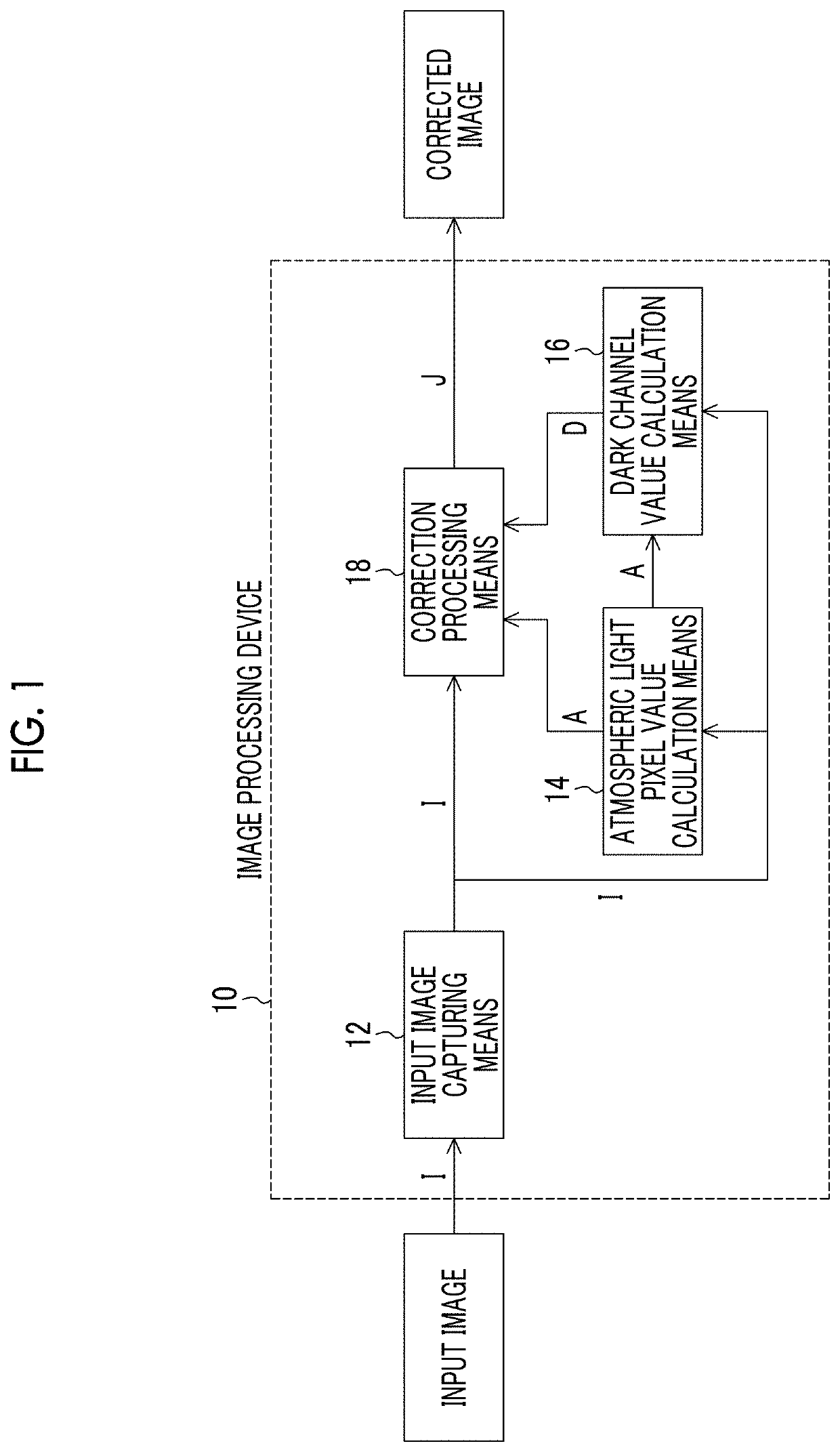
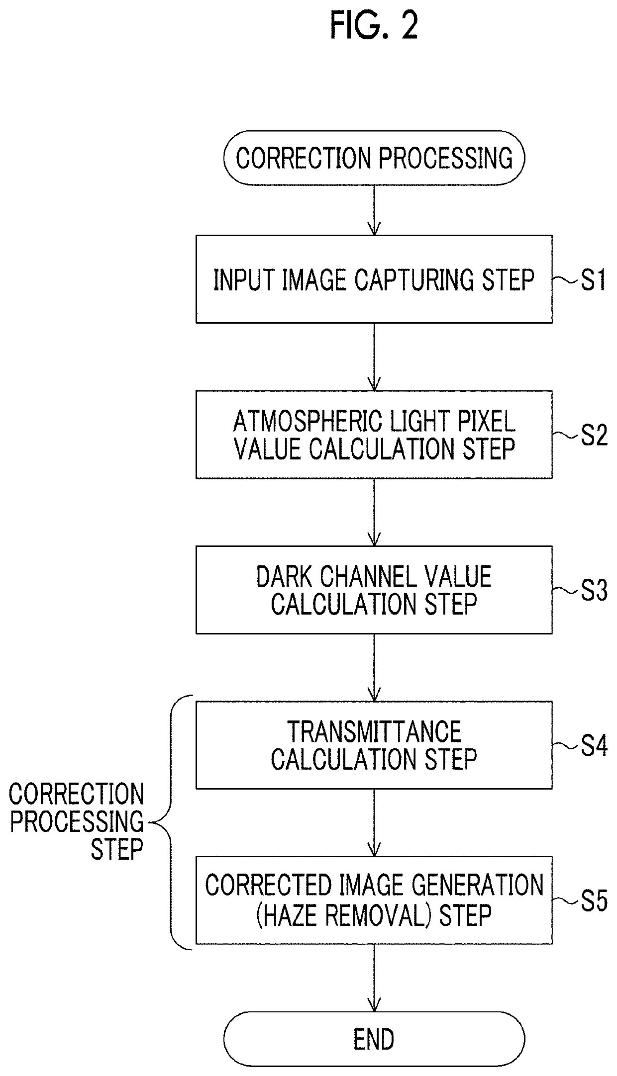
The present invention provides an image processing device and an image processing method capable of removing haze (reducing the effect of haze) without losing detail of a high-luminance subject. In the aspect of the present invention, the input image I is represented by I=J·t+A·(1−t) where an original image is J, an atmospheric light pixel value is A, and a transmittance is t. In this case, a dark channel value D of each pixel of the input image I is calculated, and is associated with the transmittance t having a value monotonically decreasing for each pixel of which D ranges from 0 to 1 and associated with the transmittance t having a value monotonically increasing for each pixel which corresponds to haze and of which D ranges from 1 to Dmax. In such a manner, the original image J is generated as a corrected image.

Description

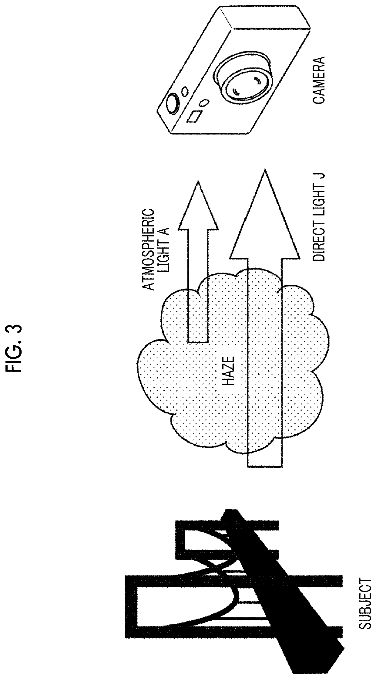
CROSS-REFERENCE TO RELATED APPLICATIONS[0001]The present application is a Continuation of PCT International Application No. PCT / JP2016 / 075456 filed on Aug. 31, 2016 claiming priority under 35 U.S.C § 119(a) to Japanese Patent Application No. 2015-191762 filed on Sep. 29, 2015. Each of the above applications is hereby expressly incorporated by reference, in their entirety, into the present application.BACKGROUND OF THE INVENTION1. Field of the Invention[0002]The present invention relates to an image processing device and an image processing method, and relates to an image processing device and an image processing method capable of removing haze such as mist or fog included in an image.2. Description of the Related Art[0003]In an image captured with a camera, a scene may be whitened due to haze such as mist or fog, haze is superimposed on an image (hereinafter referred to as an original image) in which original colors of a subject as an imaging target are directly reflected, and in so...

Claims


Application Information

Patent Timeline
Patent Type & Authority Patents(United States)
IPC IPC(8): G06T5/00
CPCG06T5/002G06T2207/20182G06T5/003G06T5/50H04N1/4076H04N1/6086G06T2207/10024G06T2207/20221H04N9/646H04N23/71H04N23/10H04N23/84H04N1/409
Inventor FUJIKAWA, TETSUYA
Owner FUJIFILM CORP
Learn More