System and method for rejecting afocal light collected from an in vivo human retina

a technology of in vivo human retina and afocal light, which is applied in the field of imaging, can solve the problems of limited resolvable object size, limited sensitivity of the optical system to small objects, and both systems have several limitations, so as to achieve greater source resolution and increase spatial

Active Publication Date: 2018-08-28
NEUROVISION IMAGING INC
View PDF39 Cites 0 Cited by
  • Summary
  • Abstract
  • Description
  • Claims
  • Application Information

AI Technical Summary

Benefits of technology

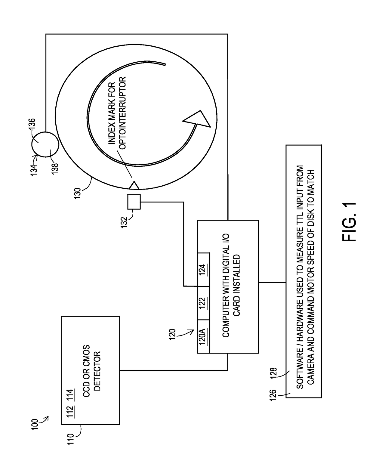
[0009]The system and method for rejecting afocal light collected from an in vivo human retina utilizes an amalgamation of these two systems, while simultaneously coupling already available technology utilized in the field of confocal microscopy and emerging technologies in coded optical systems. To achieve confocality, a pinhole must be utilized as we've described above, to eliminate haze from the return image. Existing systems and methods rely on the pinhole utilizing a fixed single point detector, such as a photodiode or photomultiplier, sitting behind a pinhole fixed in space. The image is scanned by moving the effective detection point across a field of the retina. The system and method instead fixes the illumination and return paths, and moves the pinhole over the surface of the detector and may be utilized to interact with the delivery light as well. This is effectively the same solution employed on spinning disk confocals utilized in modem fluorescent microscopy, such as the Yokagawa CSU XI, which relies on a Nipkow Disk including microarray lens technology, to maximize the collection of all focal light through the disk. While utilizing the basic premise of a scanning pinhole array, as is utilized on the systems for microscopy, the system provides several new and novel improvements upon current technology. Firstly, all current spinning disk systems are only utilized on microscopes, have effective pinhole sizes which are matched to high numerical aperture oil immersion lenses for microscopy, and are of a size and configuration as to provide stability for very high magnification imaging (i.e. heavy and large).
[0010]It is an object of the present invention to provide a system and method for rejecting afocal light collected from an in vivo human retina that sacrifices weight for the advantages of portability, while sacrificing rigidity knowing that small vibrations won't affect the lower magnification images collected on our device.
[0013]It is an object of the present invention to provide a system and method for rejecting afocal light collected from an in vivo human retina that does not utilize a pinhole but instead provides a slit, series of cuts or shapes on the disk, to make a compromise between focal specificity and overall collection efficiency.
[0014]It is an object of the present invention to provide a system and method for rejecting afocal light collected from an in vivo human retina that provides for the owner or operator of the device to exchange spinning disks. Using the system and method the operator may choose between numerous focal specificities, allowing for greater control over the image quality.
[0017]It is an object of the present invention to provide a system and method for rejecting afocal light collected from an in vivo human retina that utilizes a series of optical shapes, or codes, similar to other structured illumination systems, to illuminate the image field several times, which when collected and processed in software such as non-transitory storage media, yield measurements of both optical noise and signal, allowing the non-transitory storage media to subtract the noise from the final image, and infer greater source resolution via scattering analysis, achieving a similar result as a confocal system but with an increase in spatial resolution.

Problems solved by technology

Both systems have several limitations.
The flood illumination fundus camera has the benefit of lower cost, as the device relies on a fluorescent exciting gas-arc, white light, or LED excitation or delivery source, but because this system delivers illumination in both a focal plane and out of focus planes, numerous artifacts and reflections are present in the image, and are visualized as sources of noise and / or reflection areas, where the image is blocked entirely and thereby unusable in those regions.
In addition to the artifacts produced, the afocal haze present in the return image limits the optical system's sensitivity to small objects.
While the resolution of the system is not limited to haze, the minimum resolvable object size is limited by the minimally detectable background to signal level.
A confocal laser scanning ophthalmoscope or CLSO overcomes several of the limitations found in a flood illumination system, but at a relatively great increase in cost and component complexity.
While these advantages do result in substantial effective resolution improvements and image quality improvements, they come at a relatively great cost and complexity increase.
Lasers with the required performance specifications utilized on a CLSO have a high cost for a single wavelength, and as most operators and owners want several colors in the image, multiple lasers must be coupled to the system.
In addition, should one of the beam steering systems fail, the potential for damage to the subject exists.

Method used


Image

  • System and method for rejecting afocal light collected from an in vivo human retina
  • System and method for rejecting afocal light collected from an in vivo human retina
  • System and method for rejecting afocal light collected from an in vivo human retina

Examples


Embodiment Construction

[0029]Various aspects of the illustrative embodiments will be described using terms commonly employed by those skilled in the art to convey the substance of their work to others skilled in the art. However, it will be apparent to those skilled in the art that the present invention may be practiced with only some of the described aspects. For purposes of explanation, specific numbers, materials and configurations are set forth in order to provide a thorough understanding of the illustrative embodiments. However, it will be apparent to one skilled in the art that the present invention may be practiced without the specific details. In other instances, well-known features are omitted or simplified in order not to obscure the illustrative embodiments.

[0030]Various operations will be described as multiple discrete operations, in turn, in a manner that is most helpful in understanding the present invention. However, the order of description should not be construed as to imply that these op...


PUM


Abstract

A system and method for rejecting afocal light collected from an in vivo human retina is disclosed. The system may include a detector, a server system being in communication with the detector and a memory system with a rejection of collected afocal light and a disk having an optointerruptor and a motor, which is speed controlled via a non-transitory storage media. The method includes utilizing a series of optical shapes or codes, similar to other structured illumination systems, illuminating the series of optical shapes or codes several times, collecting and processing the series of optical shapes or codes yielding measurements of optical noise and optical signal and subtracting the noise and signal from the final image.

Description

[0001]This application claims priority to U.S. Provisional Application 61 / 793,819 filed on Mar. 15, 2013, the entire disclosure of which is incorporated by reference.BACKGROUND OF THE INVENTION[0002]Field of the Invention[0003]The present invention is a system and method for imaging. More specifically, the present invention is a system and method for rejecting afocal light collected from an in vivo human retina.[0004]Description of the Related Art[0005]Current imaging modalities for the human retina rely on one of two distinct methods: flood Illumination, wherein a standard broadband wide field illumination source is delivered into the retina, and then all return light is imaged, or via a confocal laser scanning ophthalmoscope, wherein a point of light is delivered into the retina via a combination of polygonal mirrors and a galvanometric motor and mirrors, and the return signal from this point is simultaneously imaged to a photomultiplier tube, PMT detector, avalanche photodiode or...

Claims


Application Information

Patent Timeline
Patent Type & Authority Patents(United States)
IPC IPC(8): A61B3/14G02B21/00A61B3/15A61B3/00A61B3/135A61B3/10
CPCA61B3/156A61B3/0008A61B3/0025G02B21/0044A61B3/135G02B21/0004G02B21/0012A61B3/1025
Inventor BLANCO, AUSTINVERDOONER, STEVENBIGGS, DAVID
Owner NEUROVISION IMAGING INC
Why Eureka
Try Eureka