Intubation device

a technology of intubation device and trachea, which is applied in the field of intubation device, can solve the problems of death or disability, inability to achieve, and considerable skill, and achieve the effect of endotracheal intubation, and sometimes inability to achiev

Active Publication Date: 2020-01-14
AIRWAY MEDICAL INNOVATIONS PTY LTD
View PDF17 Cites 2 Cited by
  • Summary
  • Abstract
  • Description
  • Claims
  • Application Information

AI Technical Summary

Benefits of technology

[0044]Typically the retention tabs are configured to prevent the endotracheal tube from being displaced from the channel unless the endotracheal tube is positively removed by a user.
[0051]Typically the blade is hingedly connected to the handle to thereby allow the blade to be moved between an operational configuration and a collapsed configuration.
[0060]d) a tube movement mechanism in the handle for moving the endotracheal tube through the channel to thereby advance the endotracheal tube, the tube movement mechanism including a digit interface for allowing the user to operate the tube movement mechanism using one or more digits of the hand that is holding the intubation device, to thereby allow the user to hold the intubation device and advance the endotracheal tube in an endotracheal intubation procedure using a single hand.

Problems solved by technology

However endotracheal intubation is a high risk procedure which can lead to death or disability, requires considerable skill and occasionally cannot be accomplished.
Even to highly trained professionals, it is often difficult and sometimes unsuccessful.
This procedure requires extraordinary skills; it is easier for the endotracheal tube to follow the path towards the oesophagus, it is often difficult to obtain a good view of the larynx, and even with a good view, it is difficult sometimes to introduce the endotracheal tube.
Any delay in successfully finalising the procedure is a serious complication, and may potentially be fatal.
Often, because of anatomical variations and challenges, and despite an adequate technique, direct visualisation is difficult.
Unfortunately, with the conventional laryngoscope and conventional procedure, the operator is utilising both hands and the hand being used to manually introduce the endotracheal tube cannot be used to manipulate anatomical structures to facilitate the procedure.
Furthermore, a second operator could not have direct visual access to the entrance of the larynx to help manipulating these structures and will interfere with the vision of the first operator, as the mouth opening, through which the first operator is obtaining the view, is very limited and the operator performing the intubation procedure will usually be in the best viewing position.
Due to the degree of difficulty of the procedure itself, together with the seriousness of the potential complications, this procedure will only be performed by highly skilled professionals.
This difficulty and serious complication risk have also meant that the procedure, and the instruments used to perform it, has essentially remained unchanged for decades.
The physicians and other professionals who perform endotracheal intubations are unwilling to use new devices or to change the way this is conventionally done, given the difficulties and risks.
However, the automatic operation of this device requires a complex arrangement of hardware with a significantly different configuration to conventional laryngoscopes, resulting in a relatively large and costly device compared to conventional laryngoscopes.
The positioning of the tube driver in particular is detrimental to the ergonomics of the instrument and may interfere with operator movements or anatomical structures during a procedure.
However, the laryngoscope disclosed in this document only provides a mechanism for advancing a fiberoptic tube, not an endotracheal tube.
However, the device disclosed in this document lacks a laryngoscope blade and has a significantly different configuration and operational ergonomics compared to conventional laryngoscopes.

Method used


Image

  • Intubation device
  • Intubation device
  • Intubation device

Examples


Embodiment Construction

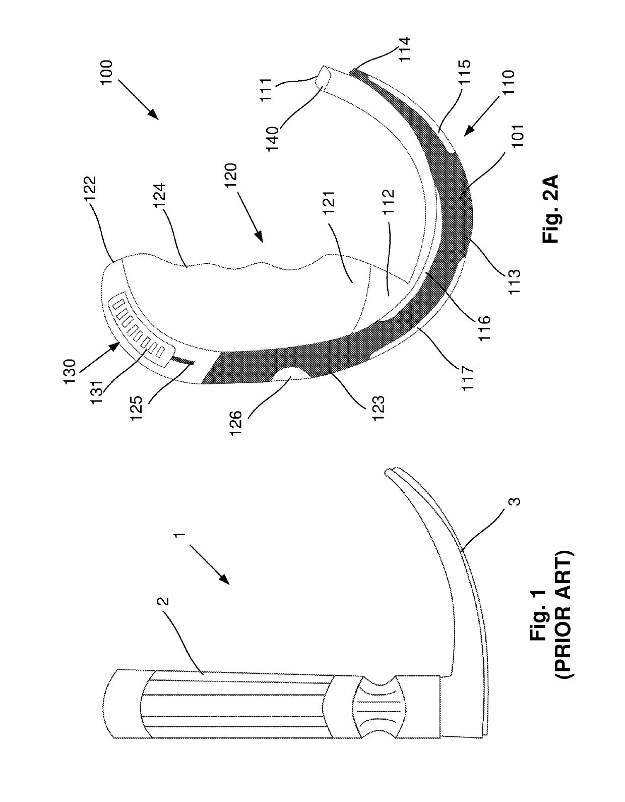
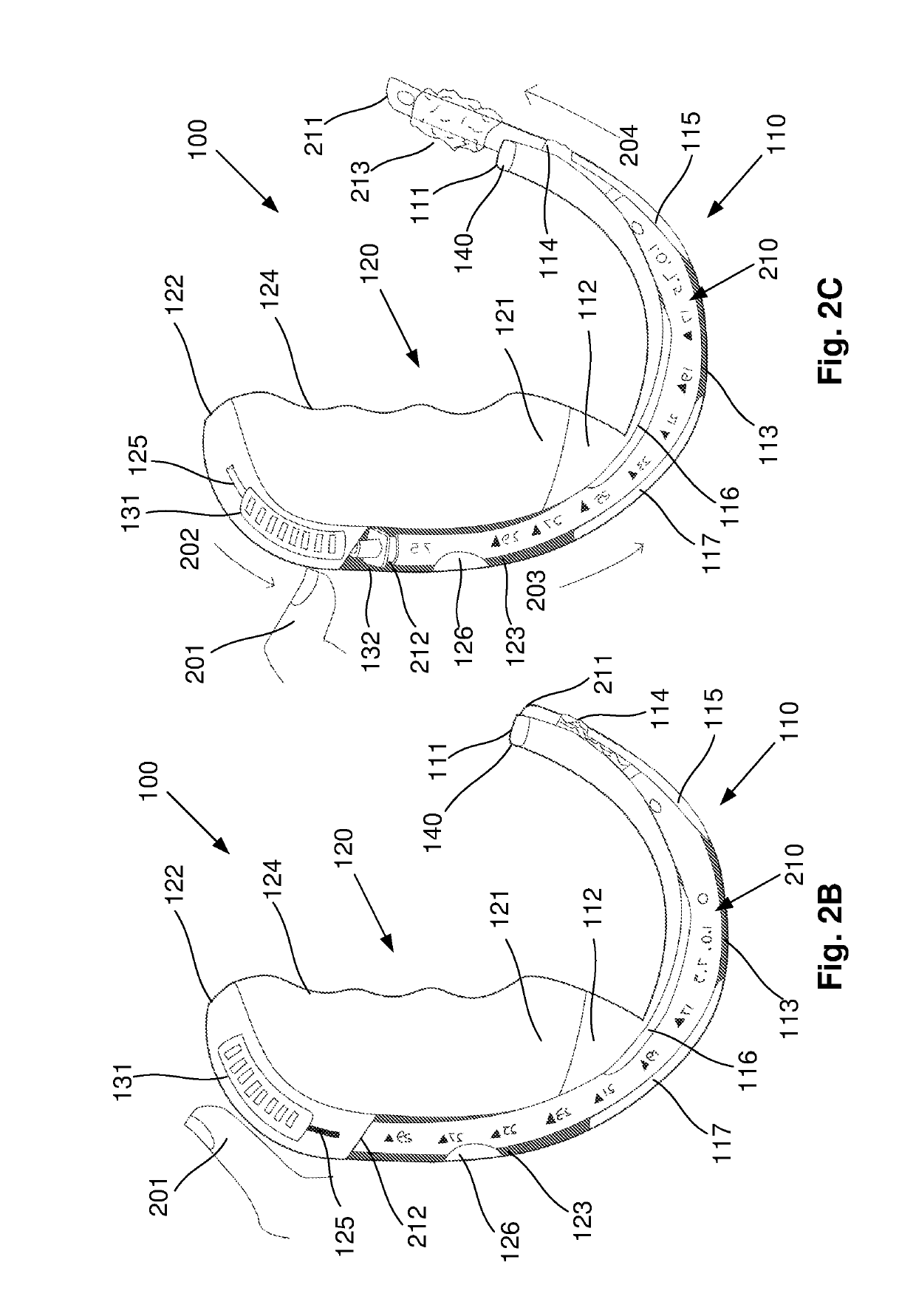
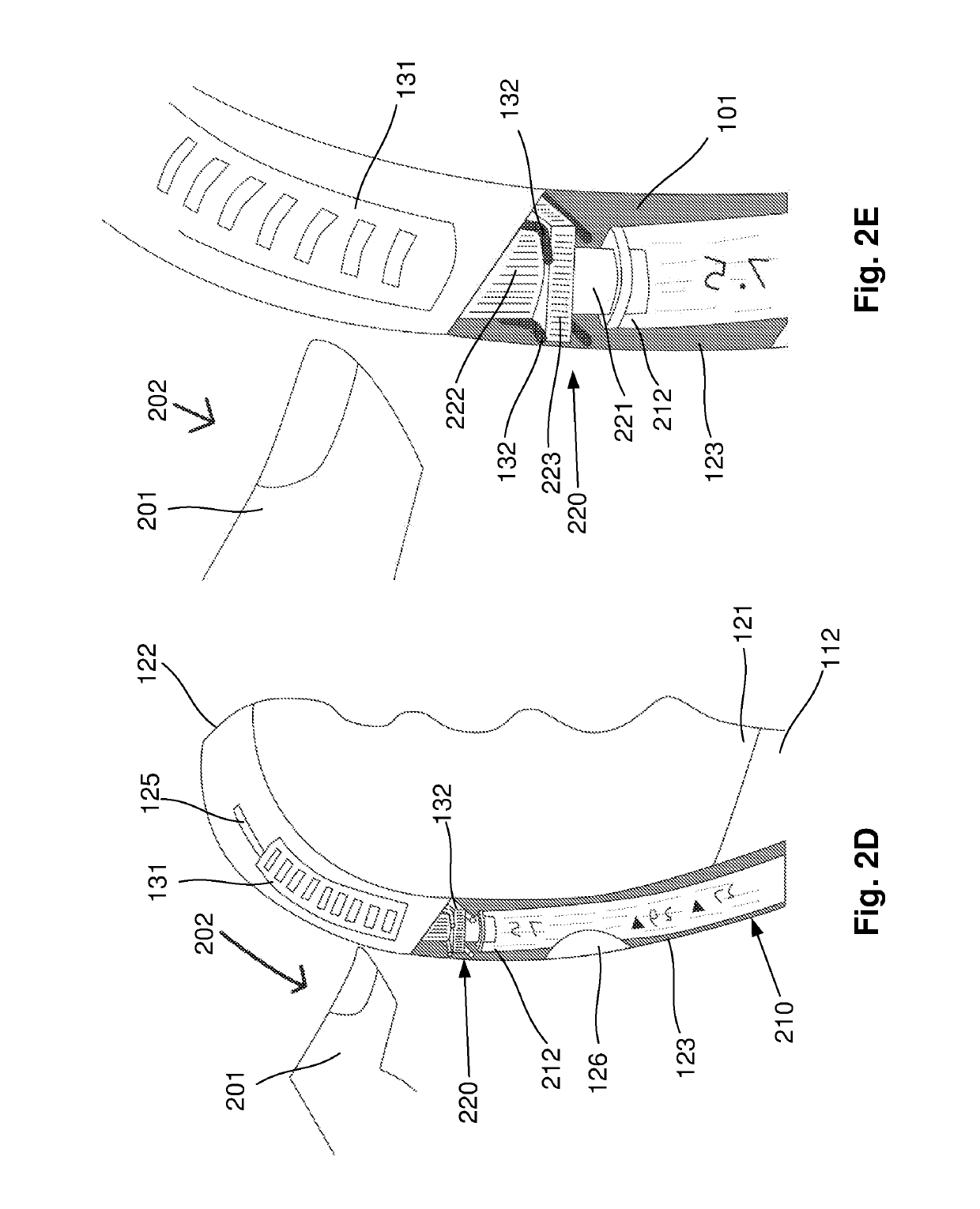
[0091]An example of an intubation device 100 for use in an endotracheal intubation procedure will now be described with reference to FIGS. 2A to 2G.

[0092]With regard to FIG. 2A, the intubation device 100 includes a laryngoscope blade 110 having a tip 111 and a base 112. A handle 120 is attached to the base 112 of the blade 110 for allowing the intubation device 100 to be held in a hand of a user.

[0093]The intubation device 100 also includes a channel 101 for receiving an endotracheal tube 210, as shown in FIG. 2B. The channel 101 includes a blade channel portion 113 extending along the blade substantially from the tip 111 to the base 112, and a handle channel portion 123 extending partially along the handle 120 from the blade channel portion 113. The blade channel portion 113 includes an outlet 114 proximate to the tip 111 for allowing a distal end 211 of the endotracheal tube 210 to be advanced from the outlet 114, as shown in FIG. 2C.

[0094]The intubation device 100 further include...


PUM


Abstract

An intubation device for use in an endotracheal intubation procedure, the intubation device including: a laryngoscope blade having a tip and a base; a handle attached to the base of the blade for allowing the intubation device to be held in a hand of a user; a channel for receiving an endotracheal tube, the channel including a blade channel portion extending along the blade substantially from the tip to the base and including an outlet proximate to the tip for allowing a distal end of the endotracheal tube to be advanced from the outlet and a handle channel portion extending partially along the handle from the blade channel portion; and a tube movement mechanism in the handle for moving the endotracheal tube through the channel to thereby advance the endotracheal tube, the tube movement mechanism including a thumb interface for allowing the user to operate the tube movement mechanism using a thumb of the hand that is holding the intubation device, to thereby allow the user to hold the intubation device and advance the endotracheal tube in an endotracheal intubation procedure using a single hand.

Description

BACKGROUND OF THE INVENTION[0001]The present invention relates to an intubation device for use in an endotracheal intubation procedure.DESCRIPTION OF THE PRIOR ART[0002]Endotracheal intubation is the procedure through which a medical professional introduces a flexible plastic conduit, an endotracheal tube, generally through the mouth and into the trachea. This allows artificial ventilation, which is required when the breathing ability is compromised by an illness or injury in an emergency situation or is interfered by drug-induced depression during surgery. It is a universal procedure and is performed in the same fashion all over the world.[0003]Every day thousands of intubations are performed by a diverse range of professionals, particularly anaesthetics specialists, intensivists, emergency physicians and pre-hospital medics and paramedics. However endotracheal intubation is a high risk procedure which can lead to death or disability, requires considerable skill and occasionally ca...

Claims


Application Information

Patent Timeline
Patent Type & Authority Patents(United States)
IPC IPC(8): A61B1/267A61B1/00A61B1/06A61B1/018A61M16/04
CPCA61B1/267A61B1/00147A61B1/018A61M16/0488A61B1/0676A61M16/0463A61M16/04A61M16/0434A61M2205/8206A61B1/00032A61B1/00055A61B1/00133A61B1/00042A61M2205/586A61B1/00039
Inventor ALONSO BABARRO, JULIO MIGUEL
Owner AIRWAY MEDICAL INNOVATIONS PTY LTD
Why Eureka
Try Eureka