Sputum suction device for pneumology department

An intubation and side end face technology, applied in the field of medical appliances, can solve the problems of inconvenient holding of the sputum suction tube, hypoxia of the patient, easy suction injury of the sputum suction device, etc. Effect

Pending Publication Date: 2022-05-27
杨新宇
View PDF1 Cites 2 Cited by
  • Summary
  • Abstract
  • Description
  • Claims
  • Application Information

AI Technical Summary

Problems solved by technology

[0006] The purpose of the present invention is to provide a sputum suction device for respiratory department to solve the problems in the prior art that the sputum suction device is easy to suck the mucous membrane, the sputum suction tube is inconvenient to hold, and the patient is likely to cause hypoxia during the sputum suction process.

Method used


Image

  • Sputum suction device for pneumology department
  • Sputum suction device for pneumology department
  • Sputum suction device for pneumology department

Examples


Embodiment Construction

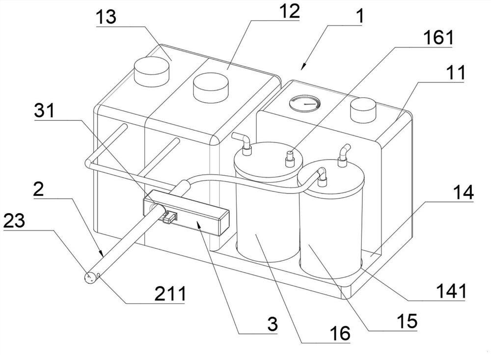
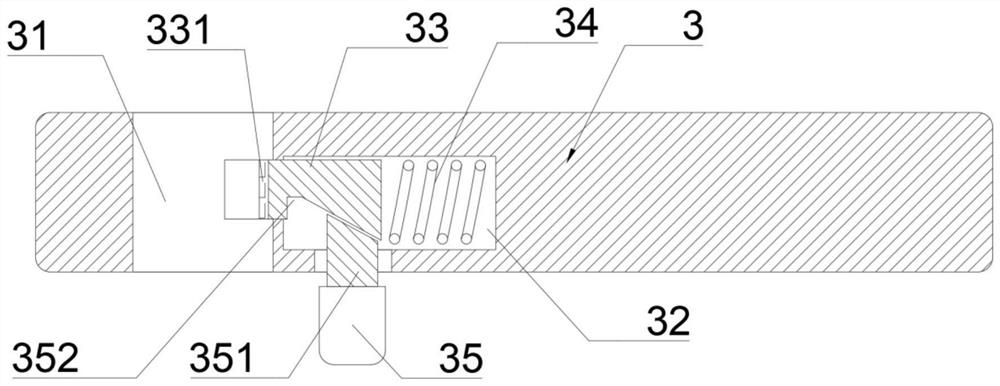
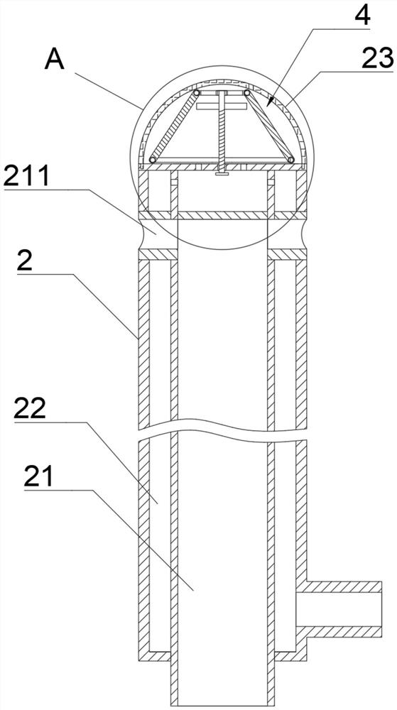
[0025] see figure 1 , a sputum suction device for respiratory department, comprising a sputum suction device main body 1 and an intubation tube 2, the upper end of the sputum suction device main body 1 is equipped with a vacuum machine 11, an oxygen generator 13 and an atomizer 12, and the front end of the vacuum machine 11 is installed. A placing table 14 is provided on which a medicine storage tank 16 and a sputum storage tank 15 are placed. The top of the sputum storage tank 15 is respectively connected to the center of the vacuum machine 11 and the intubation tube 2 through a rubber tube. The atomizer 12 is connected through a rubber tube, and the oxygen generator 13 and the atomizer 12 are connected through the rubber tube with the side wall of the cannula 2. The end face is provided with a sputum suction hole 211, the front end face of the intubation tube 2 is provided with a first air outlet 221, the intubation tube 2 is a double-layer structure, the center of the intub...


PUM


Abstract

The sputum suction device for the pneumology department comprises a sputum suction device body and an intubation tube, a vacuum machine, an oxygen generator and an atomization machine are arranged at the upper end of the sputum suction device body, a placement table is arranged at the bottom of the front end face of the vacuum machine, and a medicine storage tank and a sputum storage tank are arranged on the placement table; the top of the sputum storage tank is in through connection with the center of the vacuum machine and the center of the intubation tube through rubber tubes, the medicine storage tank is in through connection with the atomizer through a rubber tube, the oxygen generator and the atomizer are in through connection with the side wall of the intubation tube through rubber tubes, a grip is arranged at the outer end of the intubation tube, and sputum suction holes are formed in the side end face of the intubation tube. A first air outlet is formed in the front end face of the cannula, the cannula is of a double-layer structure, a sputum suction pipe is arranged in the center of the cannula, an oxygen supply pipe is arranged on the outer layer of the cannula, a sputum suction hole is in through connection with the sputum suction pipe, the first air outlet is in through connection with the oxygen supply pipe, and a protective ball is arranged at the front end of the cannula. According to the invention, the convenience and stability of equipment operation are improved.

Description

technical field [0001] The invention belongs to the technical field of medical appliances, in particular to a sputum suction device for respiratory department. Background technique [0002] After tracheotomy, due to the formation of a short circuit of breathing, the gas with insufficient relative humidification enters the airway directly from the trachea, causing the frequency of ciliary movement to decrease or stop, reducing the ability of the mucociliary system to remove foreign bodies, destroying the body's natural defense mechanism, and making it easy to surround The secretion accumulated in the one-time large-capacity low-pressure air bag descends into the respiratory tract and becomes a place for bacteria to multiply. The gas entering and leaving the respiratory tract loses the function of nasal cleaning, filtration and humidification. Bloody phlegm scabs will be formed when the incision granulation tissue capillaries rupture and hemorrhage. [0003] The existing sput...

Claims


Application Information

Patent Timeline
Patent Type & Authority Applications(China)
IPC IPC(8): A61M1/00A61M16/16A61M31/00
CPCA61M16/16A61M31/00
Inventor 杨新宇
Owner 杨新宇
Why Eureka
Try Eureka