Brake disk

Active Publication Date: 2020-01-14
DR ING H C F PORSCHE AG
View PDF17 Cites 0 Cited by
  • Summary
  • Abstract
  • Description
  • Claims
  • Application Information

AI Technical Summary

Benefits of technology

[0007]A brake disk according to aspects of the invention is distinguished by the fact that the securing ring comprises a number of spring elements which are spaced apart from one another in the circumferential direction of the securing ring, the spring elements and at least some of the projections of the brake disk hat being configured in such a way that, in a target assembly position of the securing ring, the spring elements interact with the projections which correspond with them in such a way that they retain the securing ring on the brake disk hat. The special configuration of at least some of the projections of the brake disk hat and of the securing ring with its spring elements achieves particularly secure retention of the friction ring on the brake disk hat in the axial direction. Moreover, the spring elements make a compensation of manufacturing tolerances possible.
[0011]There is the possibility in one preferred embodiment that the spring elements are arranged equidistantly with respect to one another in the circumferential direction of the securing ring. As a result, a uniform distribution of the retaining force of the securing ring in the circumferential direction is achieved.
[0013]The securing ring can preferably have an annular face which bears on the outside against the projections and intermediate spaces, of the friction ring and the brake disk hat which engage into one another in pairs. In particular, the annular face can be configured in such a way that it at least partially, preferably completely, covers the projections and intermediate spaces of the friction ring and the brake disk hat which engage into one another in pairs. In particular, the annular face of the securing ring makes a flush-mounted closure of the inner side of the friction ring possible.

Problems solved by technology

This type of securing is appropriately suitable only for wheel flanges of a relatively flat design, but not for brake disk hats of a higher design.

Method used


Image

  • Brake disk
  • Brake disk
  • Brake disk

Examples


Embodiment Construction

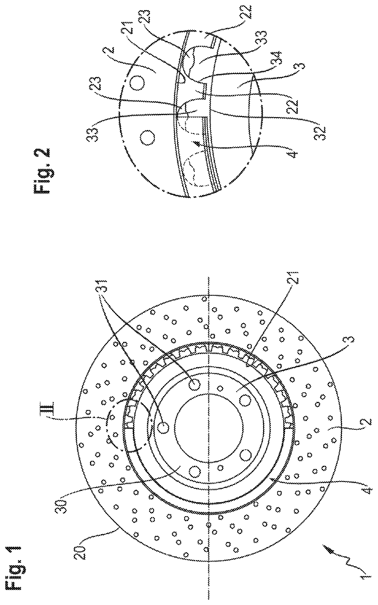
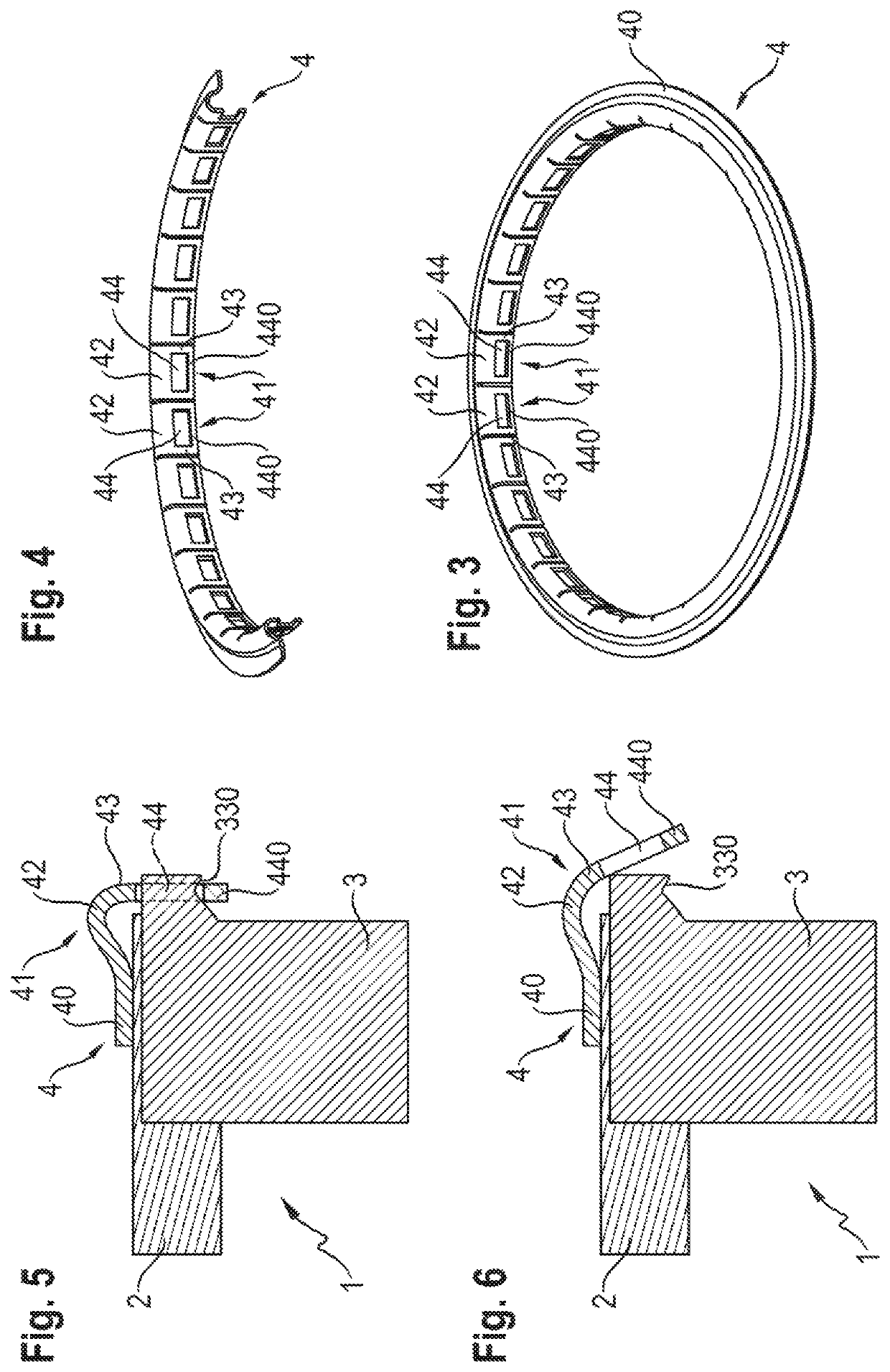
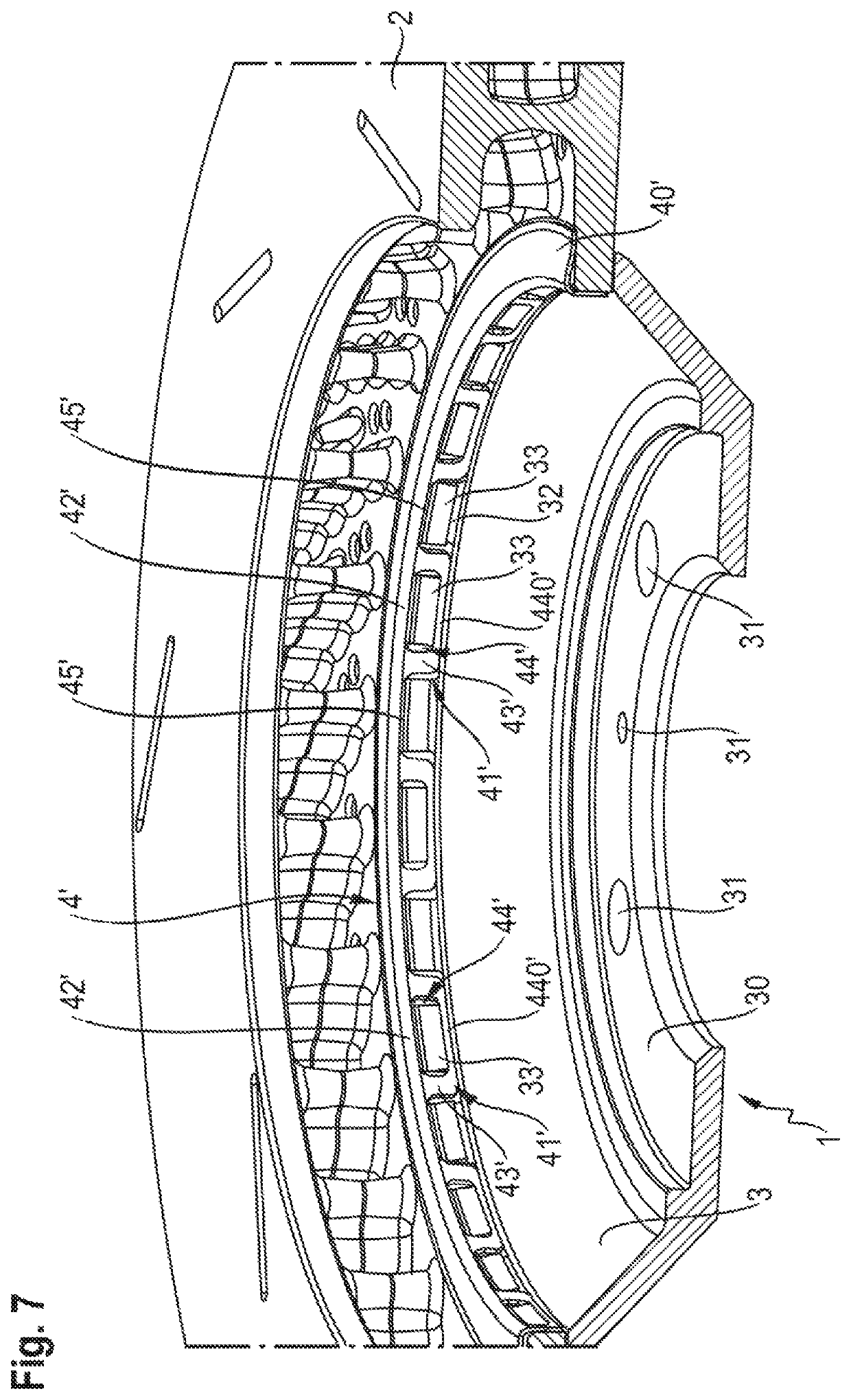
[0028]With reference to FIGS. 1 and 2, a brake disk 1 which is configured in accordance with one exemplary embodiment of the present invention comprises a friction ring 2 which has a circular outer side 20 and an inner side 21, and a separately produced brake disk hat 3. The friction ring 2 and the brake disk hat 3 are arranged concentrically with respect to one another, the friction ring 2 being connected fixedly to the brake disk hat 3 so as to rotate with it. Furthermore, the brake disk 1 has a securing ring 4 which has been illustrated merely partially in FIG. 1 and FIG. 2 (only half of it being illustrated in FIG. 1) and which serves the purpose of securing the friction ring 2 on the brake disk hat 3 in the axial direction (that is to say, perpendicularly with respect to the plane of the drawing in FIG. 1).

[0029]The friction ring 2 and the brake disk hat 3 can be produced, in particular, from different materials. For example, the brake disk hat 3 can be produced from a material...


PUM


Abstract

A brake disk includes a friction ring, a brake disk hat and a securing ring. The friction ring has an inner side, on which a plurality of projections and intermediate spaces for connecting the friction ring to the brake disk hat are disposed. The brake disk hat has, on its outer side, intermediate spaces and projections which correspond with the projections and intermediate spaces of the friction ring and are shaped to engage in a positively locking manner into the projections and intermediate spaces of the friction ring, with the result that the friction ring is connected fixedly to the brake disk hat so as to rotate therewith. The securing ring secures the friction ring on the brake disk hat in the axial direction. The securing ring includes a number of spring elements which are spaced apart from one another in the circumferential direction of the securing ring.

Description

CROSS-REFERENCE TO RELATED APPLICATION[0001]This application claims priority to German Patent Application No. DE 10 2017 116 681.5 filed Jul. 24, 2017, which is incorporated by reference herein in its entirety.FIELD OF THE INVENTION[0002]The present invention relates to a brake disk, comprising a friction ring, a brake disk hat and a securing ring, the friction ring having an inner side, on which a plurality of projections and intermediate spaces for connecting the friction ring to the brake disk hat are configured, the brake disk hat having, on its outer side, intermediate spaces and projections which correspond with the projections and intermediate spaces of the friction ring and are shaped in such a way that they engage in a positively locking manner into the projections and intermediate spaces of the friction ring, with the result that the friction ring is connected fixedly to the brake disk hat so as to rotate with it, and the securing ring being set up to secure the friction r...

Claims


Application Information

Patent Timeline
Patent Type & Authority Patents(United States)
IPC IPC(8): F16D65/12F16D65/02
CPCF16D65/123F16D2065/1368F16D2065/1392F16D2065/1316F16D2065/1344F16D65/12
Inventor HIGLE, ANDREAS
Owner DR ING H C F PORSCHE AG
Why Eureka
Try Eureka