
Head enclosing treatment hood

Inactive Publication Date: 2005-02-15
COX GERALD L
View PDF32 Cites 64 Cited by
  • Summary
  • Abstract
  • Description
  • Claims
  • Application Information

AI Technical Summary

Benefits of technology

[0011]It is a further object of the present invention to provide a neck seal which is attached to the neck ring and which does not require the end user to perform an assembly step and wherein the neck seal may be securely retained within the two-piece neck ring upon shipment by the manufacturer.
[0012]A further object of the present invention is to provide a novel hood ring design wherein the attachment point between the hood and the hood ring is not located on a working and sealing surface between the hood ring and the neck ring.
[0017]One advantage of the present design is that the upper and lower neck ring may be assembled easily with the neck seal compressed therebetween. Thus, the prior art designs which require assembly of the neck ring by stretching or by retention in specially constructed rings is overcome with a simplified design which compresses the seal between the neck ring pieces.

Problems solved by technology

However, in these designs, there is no teaching of a simplified sealing and connection-system between the hood ring and the neck ring and neck seal.
Some of the devices disclosed in the above-referenced patent have complex or difficult structures to ensure sealing between the neck ring and neck seal and also include structure which does not readily retain the proper pressure within the hood.
It is also found in these prior art devices that after repeated wear on various surfaces of the devices, the seal between the hood and the hood ring may be corrupted.
It is further noted that the prior art devices include complex or difficult attachment processes for affixing the neck seal to the neck ring or in assembly of the device.
However, theses masks have been found to be extremely uncomfortable by the respiratory patient, resulting in a decreased compliance with the prescribed treatment regimen.

Method used


Image

  • Head enclosing treatment hood
  • Head enclosing treatment hood
  • Head enclosing treatment hood

Examples


Embodiment Construction

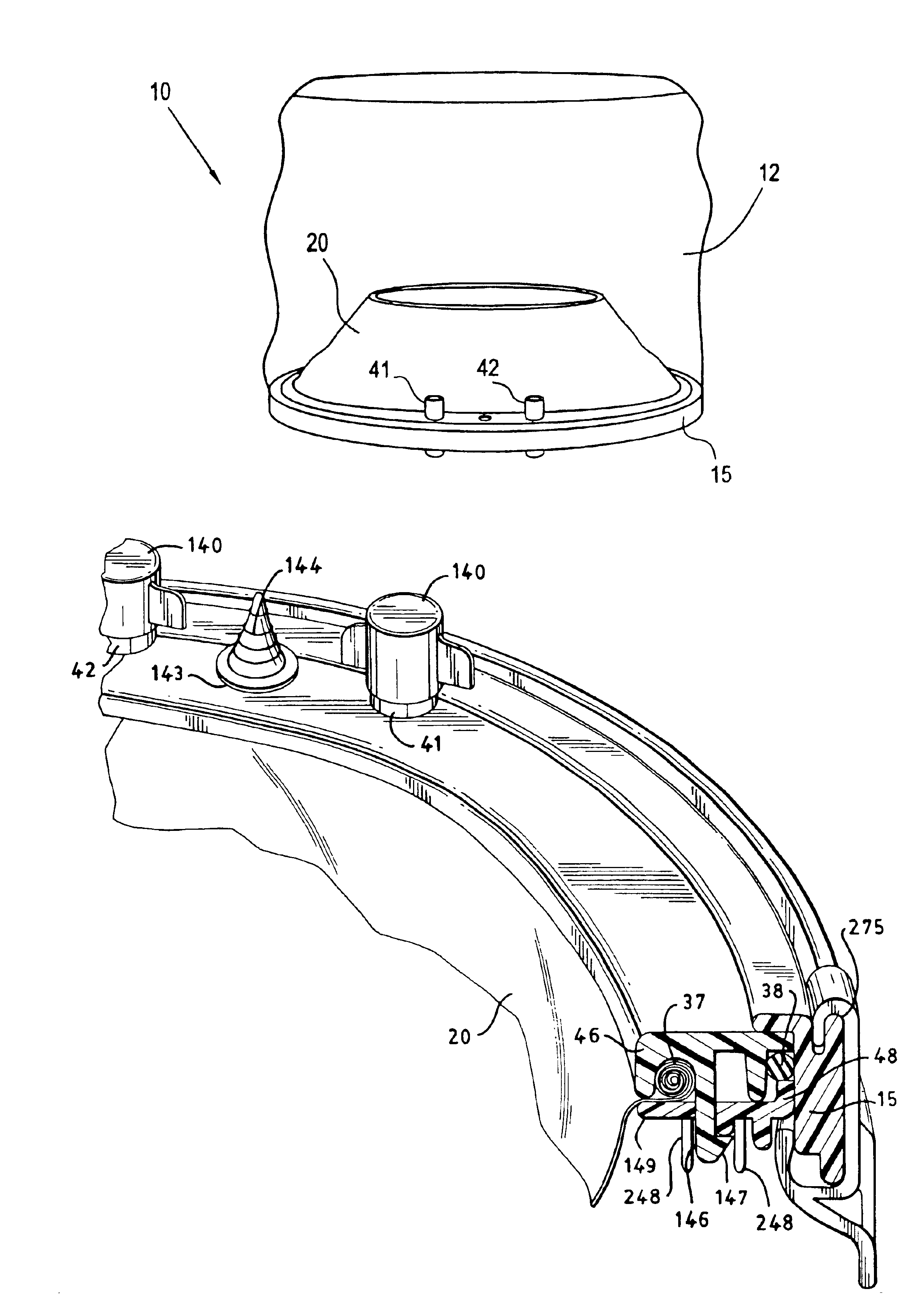
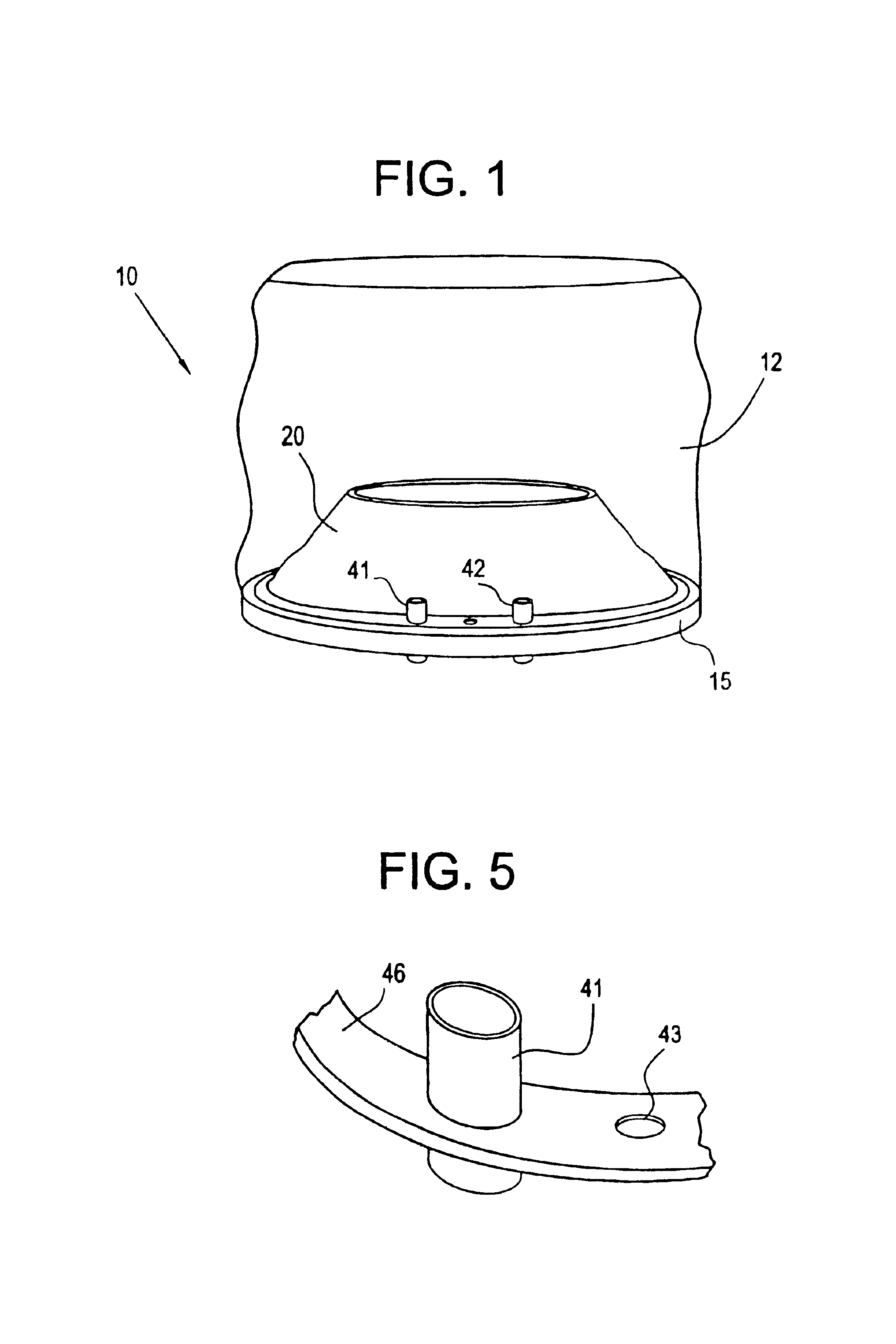
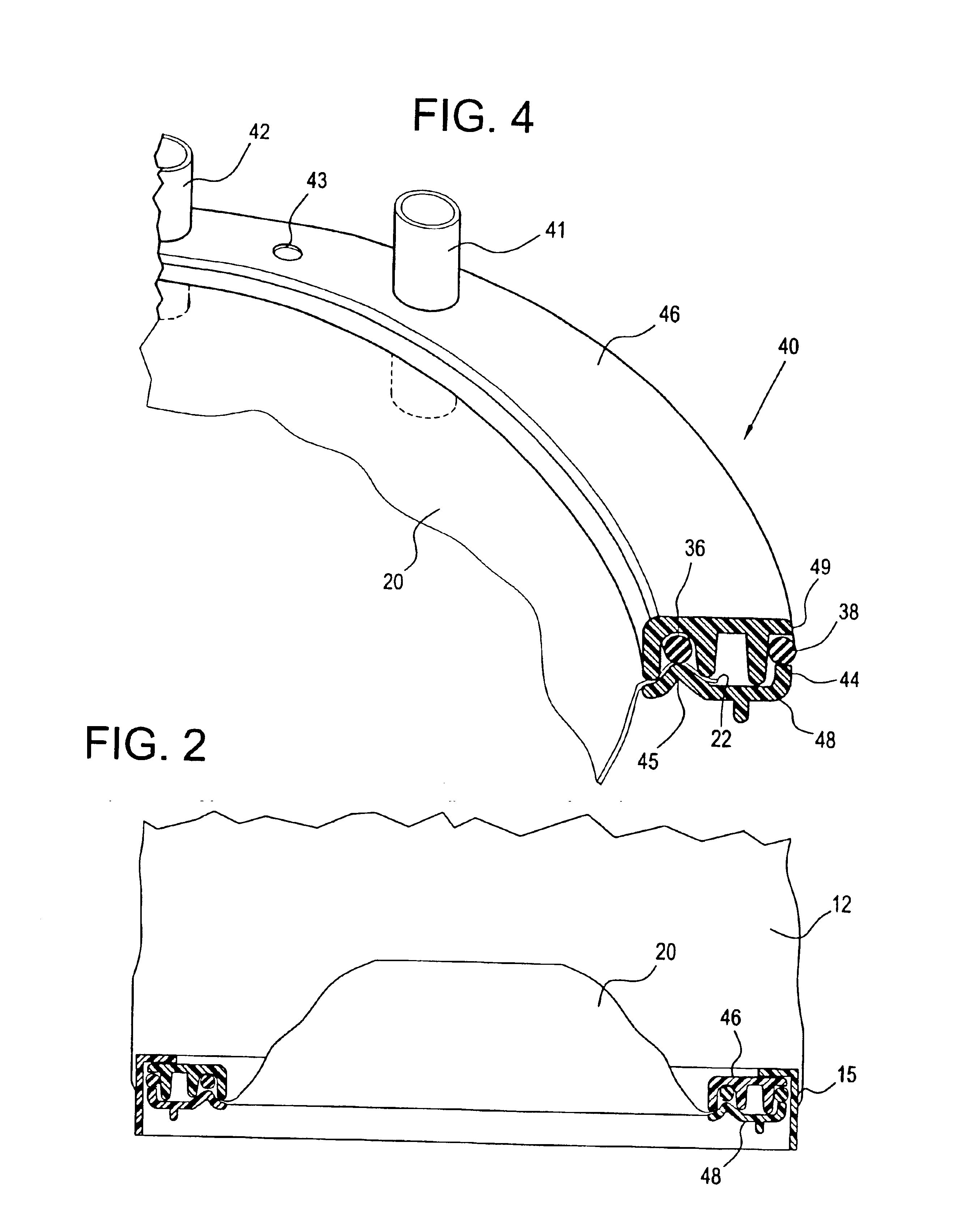
[0039]The head enclosing treatment hood of the present invention is shown in FIG. 1. As disclosed therein, the gas hood or head tent 10 is comprised of hood portion 12 which is affixed to a hood ring 15. The hood ring slides aver the upper neck ring 46 and lower neck ring 48. Upper and lower rings 46 and 48 have a neck seal 20 compressed therebetween, the neck seal 20 extending inwardly therefrom. Neck seal 20 is provided so that a gas impermeable seal may be made between the hood ring 15 and upper and lower neck rings 46 and 48 and the user's neck when the user's head is inserted into the hood portion 12. First gas port 41 and second gas port 42 are also provided for insertion and removal of gas from within the hood portion 12. First gas port 41 and second gas port 42 extend through the upper neck ring 46 and lower neck ring 48 so that ready access is provided into the interior of the hood portion 12. FIG. 9 shows the gas hood 10 placed over the head of a user 200.

[0040]The gas hoo...


PUM


Abstract

A head enclosing gas hood for treating respiratory ailments is placeable over a patient's head for providing a gas, preferably oxygenated, to said patient. The treatment gas hood has a hood portion which is connected to a hood ring. The hood ring slides over a two-piece neck ring, the two-piece neck ring consisting of an upper neck ring and a lower neck ring retained in adjacent relationship. The hood ring slides over the two-piece neck ring and forms a sealing relationship therewith. The two-piece neck ring has a neck seal retained therein and has a sealing ring on the outer periphery thereof for engagement with the working surface of the hood ring. Ports may be provided for directing a flow of a gas into and from the interior portion of the hood where the individual's head is located. The neck seal provides an adequate seal between the neck ring and the individual's neck such that a pressurized environment may be created in the hood if desired. The hood may also be used to create a local environment different from ambient, such as rich in oxygen for the patient to breathe without pressurizing the hood. The two-piece neck ring may also have a retaining ring for holding the neck seal in place after the upper and lower neck rings are retained together.

Description

CROSS REFERENCE TO RELATED APPLICATIONS[0002]This application is a continuation-in-part of U.S. Ser. No. 09 / 855,378 filed on May 15, 2001, now abandoned which is a continuation-in-part of U.S. Ser. No. 09 / 585,970 filed on Jun. 2, 2000 now U.S. Pat. No. 6,701,920.FIELD OF THE INVENTION[0003]This invention relates to a head enclosing gas hood for covering of a person's head for treating respiratory ailments.BACKGROUND OF THE INVENTION[0004]A variety of head enclosing treatment hoods have been developed for use in the delivery of gas, including oxygen, to the wearer. Such a delivery system may be desirable for directing clean air or other gases into the hood for breathing by the wearer. This function is also desirable in use as a hyperbaric oxygen treatment system wherein the patient is exposed to increased barometric pressure inside a decompression chamber, while wearing the hood device and receiving an oxygen rich environment. It may be desirable to have such a head enclosing treatme...

Claims


Application Information

Patent Timeline
IPC IPC(8): A62B17/04
CPCA62B17/04
Inventor COX, GERALD L.
Owner COX GERALD L
Learn More