Printing apparatus, liquid absorbing apparatus, and printing method

a liquid absorbing apparatus and printing method technology, applied in the direction of combustible gas purification/modification, separation process, filtration separation, etc., can solve the problems of no arrangement that detects and keeps the condition and the excess application of processed liquid, etc., to achieve satisfactory liquid absorption performance of the liquid absorbing member

Active Publication Date: 2020-01-21
CANON KK
View PDF5 Cites 0 Cited by
  • Summary
  • Abstract
  • Description
  • Claims
  • Application Information

AI Technical Summary

Benefits of technology

[0007]For example, a printing apparatus, a liquid absorbing apparatus, and a printing method according to this invention are capable of satisfactorily keeping liquid absorption performance of a liquid absorbing member that absorbs a liquid component of a formed ink image, and implementing higher-quality image formation and image printing.
[0011]The invention is particularly advantageous since it is possible to maintain the liquid absorption performance of the liquid absorbing member satisfactorily. This makes it possible to satisfactorily keep the condition of an ink image formed on a transfer member, and transfer a higher-quality image to a print medium and print the image.

Problems solved by technology

Consequently, the processed liquid may be applied excessively and used wastefully.
However, there is no arrangement that detects and keeps the condition of the liquid absorbing member.

Method used


Image

  • Printing apparatus, liquid absorbing apparatus, and printing method
  • Printing apparatus, liquid absorbing apparatus, and printing method
  • Printing apparatus, liquid absorbing apparatus, and printing method

Examples


operation example

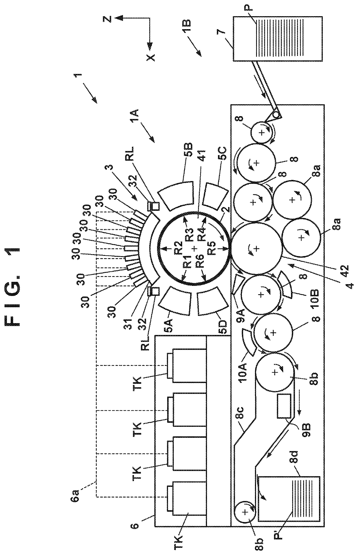
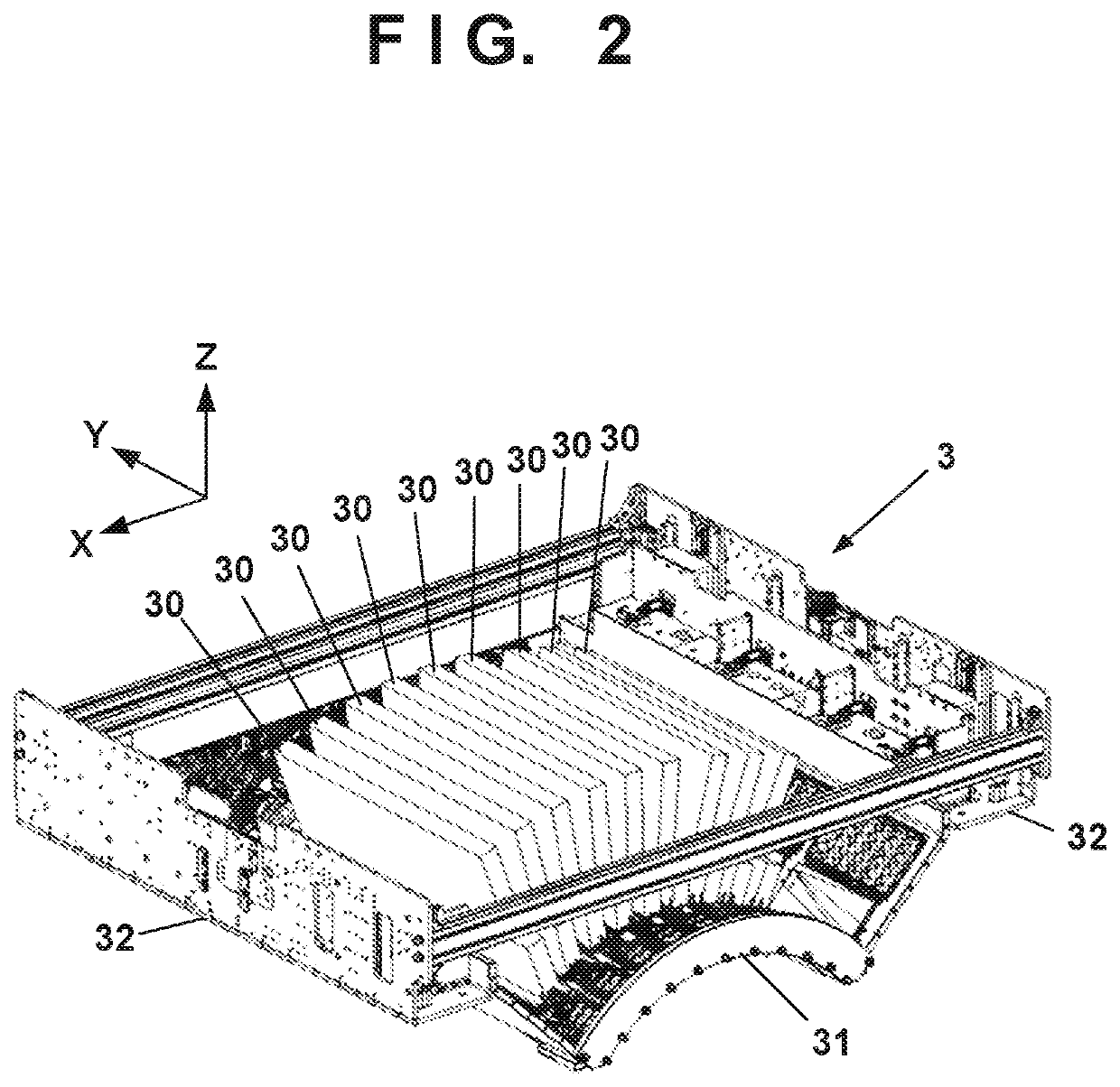
[0098]FIG. 6 is a view schematically showing an example of a printing operation. Respective steps below are performed cyclically while rotating the transfer drum 41 and the pressurizing drum 42. As shown in a state ST1, first, a reactive liquid L is applied from the application unit 5A onto the transfer member 2. A portion to which the reactive liquid L on the transfer member 2 is applied moves along with the rotation of the transfer drum 41. When the portion to which the reactive liquid L is applied reaches under the printhead 30, ink is discharged from the printhead 30 to the transfer member 2 as shown in a state ST2. Consequently, an ink image IM is formed. At this time, the discharged ink mixes with the reactive liquid L on the transfer member 2, promoting coagulation of the coloring materials. The discharged ink is supplied from the reservoir TK of the supply unit 6 to the printhead 30.

[0099]The ink image IM on the transfer member 2 moves along with the rotation of the transfer...


PUM

PropertyMeasurementUnit
pore sizeaaaaaaaaaa
temperatureaaaaaaaaaa

Abstract

A printing apparatus includes an image forming unit that forms an ink image, a transfer unit that transfers the ink image formed on a transfer member to a print medium in a transfer operation, and a liquid absorbing member that absorbs a liquid component from the ink image before the transfer operation. A recovery unit recovers absorption performance of the liquid absorbing member by applying a moisturizing liquid to the liquid absorbing member. A first estimation unit estimates, based on print data, an ink discharge amount of ink to form the ink image, and a second estimation unit estimates a liquid amount of the liquid component to be absorbed by the liquid absorbing member from the estimated ink discharge amount. In addition, a control unit controls an application amount of the moisturizing liquid by the recovery unit based on a result of estimation by the second estimation unit.

Description

BACKGROUND OF THE INVENTIONField of the Invention[0001]The present invention relates to a printing apparatus, a liquid absorbing apparatus, and a printing method, and particularly to, for example, a technique of absorbing a liquid component of ink discharged to a transfer member in a printing apparatus that transfers an image formed by discharging the ink to the transfer member to a print medium and prints the image.Description of the Related Art[0002]A technique of forming an ink image on a transfer member and transferring it to a print medium such as paper is proposed. For example, Japanese Patent Laid-Open No. 2003-182064 discloses an image formation apparatus configured to form an ink image on an intermediate member and transfer the ink image to a sheet. This apparatus includes an inkjet device that forms a primary image on the intermediate member. This apparatus also includes a zone where a coagulation body is formed in the primary image, a zone where a liquid is partially remo...

Claims


Application Information

Patent Timeline
Patent Type & Authority Patents(United States)
IPC IPC(8): B41J2/01B41J2/175B41M5/00B05C1/08B01J20/34B41J2/005B41M5/025
CPCB41J2/0057B01J20/34B41M5/0023B05C1/0813B05C1/0886B41J2/17566B41M5/0256B41J2002/012B41M7/00B05C1/083
Inventor YANAGI, YUICHIROSUGIMOTO, MASAHIRO
Owner CANON KK
Why Eureka
Try Eureka