Illumination apparatus

a technology of illumination apparatus and illumination light, which is applied in the direction of lighting and heating apparatus, fixed installation, instruments, etc., can solve the problems of insufficient light energy radiated on the road surface, energy waste, and uncomfortable feeling in the eyes of pedestrians and drivers

Active Publication Date: 2020-01-21
LEOTEK CORP
View PDF5 Cites 0 Cited by
  • Summary
  • Abstract
  • Description
  • Claims
  • Application Information

AI Technical Summary

Benefits of technology

[0005]The disclosure provides an illumination apparatus in which glare is suppressed and required illumination effect is achieved.
[0008]To sum up, in the illumination apparatus provided by the embodiments of the disclosure, the optical micro-structures featuring the multilayer stair-structures or the optical micro-structures featuring the stacked layers with at least part of the side surfaces not being aligned are adopted. Since the optical micro-structures may diffuse the light beam by refraction and reflection, glare is suppressed and required illumination effect is achieved.

Problems solved by technology

When the light-emitting diodes act as the light-emitting source for road illumination devices, problems such as severe glare caused by excessive concentration of light intensity may occur most of the time, which may easily lead to uncomfortable feeling in the eyes of the pedestrians and the drivers.
Consequently, energy waste is caused and insufficient light energy may be radiated on the road surface, and road regulations are not met as a result.
Therefore, how an illumination apparatus is designed in which required illumination effect is satisfied and glare is suppressed is an important issue for research and development.

Method used


Image

  • Illumination apparatus
  • Illumination apparatus
  • Illumination apparatus

Examples


Embodiment Construction

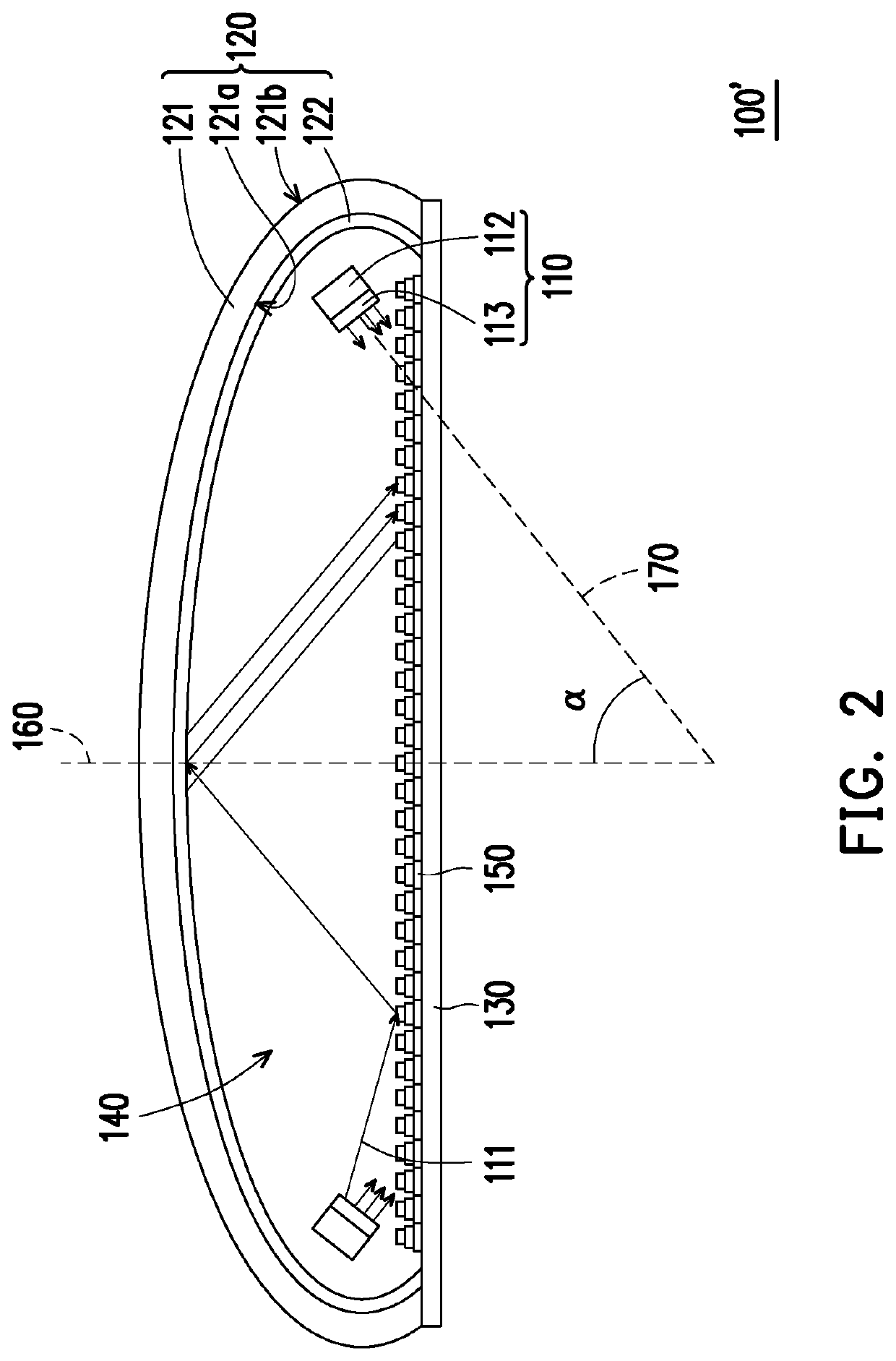
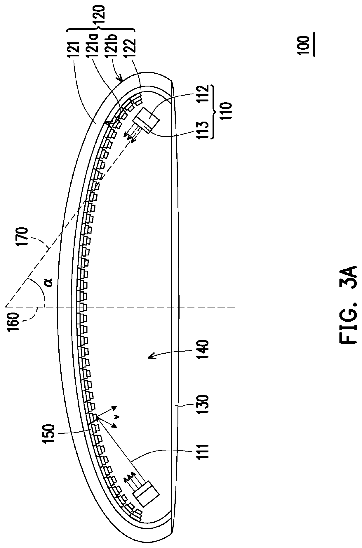
[0020]FIG. 1 is a schematic cross-sectional view of an illumination apparatus according to an embodiment of the disclosure. FIG. 2 is a schematic cross-sectional view of an illumination apparatus according to another embodiment of the disclosure. With reference to FIG. 1, an illumination apparatus 100 of this embodiment includes a reflective shell 120, a front cover 130, at least one light-emitting device 110 (plural light-emitting devices 110 are taken for example in this embodiment), and a plurality of optical micro-structures 150. In some embodiments, the illumination apparatus 100 is an outdoors road illumination apparatus, such as a street light. The front cover 130 is connected to the reflective shell 120, wherein a containing space 140 is formed between the reflective shell 120 and the front cover 130. The light-emitting devices 110 are disposed in the containing space 140 and are configured to emit a light beam 111. The optical micro-structures 150 are disposed on at least o...


PUM

PropertyMeasurementUnit
included angleaaaaaaaaaa
heightaaaaaaaaaa
thicknessaaaaaaaaaa

Abstract

An illumination apparatus includes a reflective shell, a front cover, a light-emitting device, and a plurality of optical micro-structures. The front cover is connected to the reflective shell. A containing space is formed between the reflective shell and the front cover. The light-emitting device is disposed in the containing space and is configured to emit a light beam. The optical micro-structures are disposed on at least one of the reflective shell and the front cover. Each of the optical micro-structures is a multilayer stair-structure. The optical micro-structures diffuse the light beam by refraction and reflection.

Description

CROSS REFERENCE TO RELATED APPLICATION[0001]This application claims the priority benefit of China application serial no. 201810153760.4, filed on Feb. 22, 2018. The entirety of the above-mentioned patent application is hereby incorporated by reference herein and made a part of specification.BACKGROUNDTechnical Field[0002]The disclosure relates to an optical apparatus. More particularly, the disclosure relates to an illumination apparatus.Description of Related Art[0003]Nowadays, light-emitting diodes (LEDs) are gradually adopted as a light-emitting source for road illumination. The light-emitting diodes emit light through combining the electrons and the holes to convert electric energy into light energy rather than emit light through heating or discharging. Thus, the light-emitting diodes have advantages such as quick response speeds, small volumes, electricity saving, low pollution, and long life time and are suitable for mass production. As such, the light-emitting diodes graduall...

Claims


Application Information

Patent Timeline
Patent Type & Authority Patents(United States)
IPC IPC(8): F21V5/00F21V7/00G02B27/09G02B5/02
CPCG02B5/0284F21V5/002F21V7/0066G02B27/0955G02B27/0977F21S8/00F21V13/04F21V5/04F21V5/007F21V7/0083F21V7/00F21Y2115/10F21W2131/103G02B19/0019G02B5/0215G02B5/0231G02B5/12F21V7/0008F21V7/04F21V7/0091
Inventor CHEN, KUAN-YU
Owner LEOTEK CORP
Why Eureka
Try Eureka