Optical diffusing layer, optical diffusing sheet, and optical element

a technology of optical diffusing sheet and optical element, applied in the direction of television system, instruments, roads, etc., can solve the problems of reducing visibility, unable to efficiently inhibit glare defects,

Inactive Publication Date: 2005-03-24
NITTO DENKO CORP
View PDF2 Cites 25 Cited by
  • Summary
  • Abstract
  • Description
  • Claims
  • Application Information

AI Technical Summary

Benefits of technology

[0008] An object of the present invention is to provide an optical diffusing layer in which antiglare property may be maintained and screen glare may be simultaneously controlled, when applied to an LCD in which high definition is required. Furthermore, another object of the present invention is to provide an optical diffusing sheet having the optical diffusing layer, and an optical element in which the optical diffusing sheet is prepared, and a visual display using the above-mentioned optical element.
[0011] Glare on the surface of fine concavo-convex structure is considered to be caused by a lens effect mainly produced by a light with random strength induced by the surface concavo-convex structure. In the present invention, therefore, glare is suppressed by methods in which the average of peak-to-peak distance (Sm) is controlled to be no more than 80 μm and the average of center line surface roughness (Ra) is no more than 0.25 μm and glare is decreased further by controlling the average of ten-point surface roughness (Rz) as small as possible so that Rz / Ra might become no more than 9. When the average of center line surface roughness (Ra) becomes larger, the average of ten-point surface roughness (Rz) will also usually become larger, but in the present invention, screen glare is suppressed, because the average of ten-point surface roughness (Rz) is controlled smaller as compared with the average of center line surface roughness (Ra), and a convex structure is arranged to have the same form. When the above-mentioned values go out of the above-mentioned predetermined ranges, screen glare is increased.
[0013] In the above-mentioned optical diffusing layer, it is preferable that 60° glossiness of the surface with fine concavo-convex structure is no more than 70%. A reflection is prevented and an antiglare property is developed by controlling the above-mentioned 60° glossiness into no more than 70%. The above-mentioned 60° glossiness is preferably no more than 60% and more preferably 40%-50%.
[0015] A resin coated layer having a surface concavo-convex structure are easily and certainly realized, and controlling of the above-mentioned average of center line surface roughness (Ra), average of peak-to-peak distance (Sm), and average of ten-point surface roughness (Rz) is easily realized by using particles. It is especially effective to use organic particles as particles in order to suppress screen glare. Moreover, when the ultraviolet curable resin is used, curing processing by ultraviolet rays irradiation may be applied, and a resin coated layer (optical diffusing layer) may be efficiently formed with easy processing operation.
[0016] Moreover, the present invention relates to the optical diffusing layer, further comprising a low refractive index layer having a refractive index lower than a refractive index of the resin coated layer disposed on concavo-convex structure surface of the resin coated layer that constitutes the above-mentioned optical diffusing layer. Antireflection function is given by this low refractive index layer to the optical diffusing layer and as a result a decrease in visibility of a black display of a screen, that is, so-called “white ghost” is suppressed effectively that is caused by an irregular reflection on a surface of a picture, such as a display.

Problems solved by technology

Consequently, decrease in visibility may be caused.
However, in the technology, even if a surface with fine concavo-convex structure is controlled to have the above-mentioned property in the specific range, a defect of glare cannot necessarily be efficiently inhibited.

Method used


Image

  • Optical diffusing layer, optical diffusing sheet, and optical element
  • Optical diffusing layer, optical diffusing sheet, and optical element

Examples


example 1

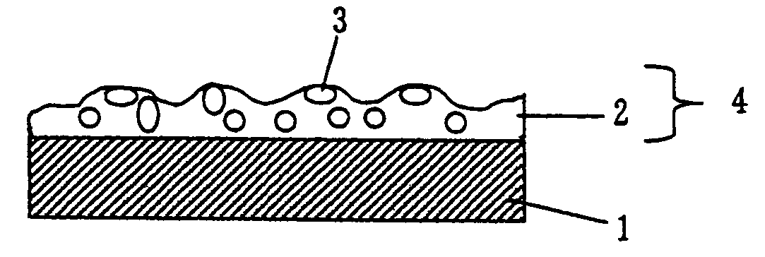
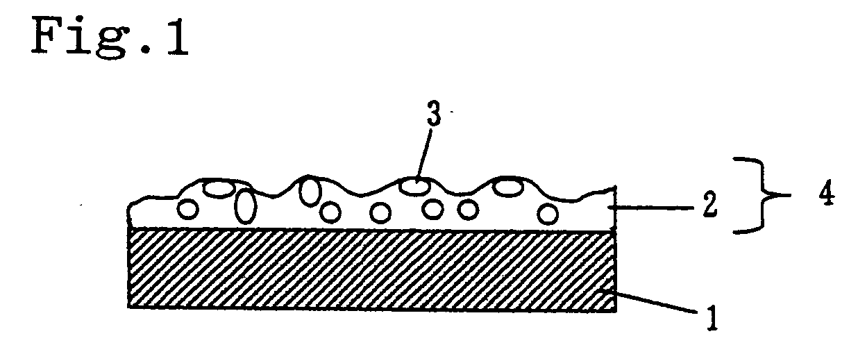
[0078] As particles, polystyrene beads having an average particle size of 3.5 μm 12 weight parts, a ultraviolet curable resin (urethane acrylate series monomer) 100 weight parts, and a benzophenone derived photo polymerization initiator 5 weight parts were dissolved in solvent (toluene) to obtain a solution with solid content of 40%. After the solution obtained was coated on a triacetyl cellulose, dried at 120□ for five minutes, the coated layer obtained was cured with ultraviolet irradiation. Thus an optical diffusing sheet having a resin coated layer with a surface of fine concavo-convex structure having a thickness of about 4 μm was produced.

example 2

[0079] In example 1, an optical diffusing sheet was produced as in example 1 except having changed the amount of polystyrene beads used into 14 weight parts.

example 3

[0080] In example 1, an optical diffusing sheet was produced as in example 1 except having changed thickness of a resin coated layer into about 3 μm.


PUM

PropertyMeasurementUnit
particle sizeaaaaaaaaaa
surface roughnessaaaaaaaaaa
Rz/Raaaaaaaaaaa

Abstract

An optical diffusing layer includes a resin coated layer having a surface fine concavo-convex structure. An average of peak-to-peak distance (Sm), an average of center line surface roughness (Ra), and an average of ten-point surface roughness (Rz) on the surface with fine concavo-convex structure satisfy specified equations, and the optical diffusing layer is capable of maintaining antiglare property and screen glare simultaneously controlled, when applied to an LCD in which high definition is required.

Description

[0001] This is a continuation of application Ser. No. 10 / 029,721, filed Dec. 20, 2001, which claims priority to Japanese Patent Application No. 2000-392255, filed Dec. 25, 2000, and the disclosure of which is incorporated herein by reference in its entirety.BACKGROUND OF THE INVENTION [0002] 1. Field of the Invention [0003] The present invention relates to an optical diffusing layer used in order to suppress decrease in visibility of a screen, an optical diffusing sheet having the optical diffusing layer concerned thereon, and further relates to an optical element in which the optical diffusing sheet concerned is prepared thereon, in a liquid crystal display (LCD), organic EL, and PDP, etc. [0004] 2. Description of the Related Art [0005] Conventionally, in picture display, such as LCD, incidence from an indoor lighting, such as a fluorescent light, or sunlight from windows, or a reflection of operator's shadow etc. given to a display unit surface sometimes aggravates visibility of p...

Claims


Application Information

Patent Timeline
Patent Type & Authority Applications(United States)
IPC IPC(8): B32B7/02B32B27/20G02B5/02G02F1/1335H04N5/72
CPCG02B5/0221Y10T428/2495G02B5/0242G02B5/0278H04N5/72Y10S428/913Y10T428/24405Y10T428/256Y10T428/24355Y10T428/254Y10T428/24942Y10T428/1036Y10T428/25Y10T428/24372G02B5/0226B29D11/00798C09K2323/03G02B5/02
Inventor MATSUNAGA, TAKUYASHIBATA, HIROSHISHIGEMATSU, TAKAYUKISATAKE, MASAYUKISHOUDA, TAKASHI
Owner NITTO DENKO CORP
Why Eureka
Try Eureka