
Dental prosthesis arrangement

a technology for dental prostheses and prostheses, applied in dentistry, dental surgery, medical science, etc., can solve the problems of inability to carry out periodontal cleaning of tooth replacements with great difficulty or not at all, and the formation of biofilms on hard surfaces such as implants, in the oral cavity of the prosthesis wearer, is unavoidabl

Active Publication Date: 2020-01-28
BREDENT
View PDF36 Cites 0 Cited by
  • Summary
  • Abstract
  • Description
  • Claims
  • Application Information

AI Technical Summary

Benefits of technology

The invention provides a dental prosthesis arrangement with a releasable attachment between the lower and upper parts, allowing for different types of attachment to be selected. This flexibility allows for a variety of dental prosthesis arrangements to be created without the need for separate connection structures for each attachment type. The holding force between the upper and lower parts is achieved through a flexible latch system that allows for independent removal and resets with a reliable hold while wearing the prosthesis. The axial press-down force prevents gaps between the upper and lower parts, ensuring a hermetic seal. Overall, the invention provides a flexible, universally usable attachment means and a reliable hold for dental prosthesis arrangements.

Problems solved by technology

However, cementing proves to be disadvantageous because in particular, periodontal cleaning of the tooth replacement can be carried out only with great difficulty or not at all.
In this regard, particularly attention must be paid to the fact that the formation of what are called biofilms on hard surfaces, such as, for example, on implants, in the oral cavity of a prosthesis wearer, is unavoidable.
However, in the case of old people, who frequently suffer from concomitant circumstances such as dementia and physical ailments, this frequently cannot be carried out.

Method used


Image

  • Dental prosthesis arrangement
  • Dental prosthesis arrangement
  • Dental prosthesis arrangement

Examples


Embodiment Construction

[0053]In the figures, components that are the same or have the same functional effect are provided with the same reference symbols.

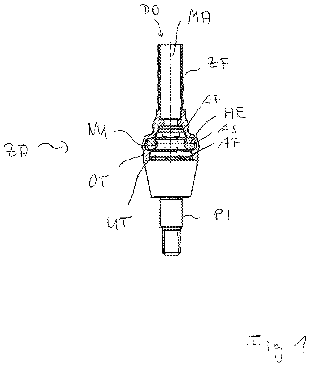
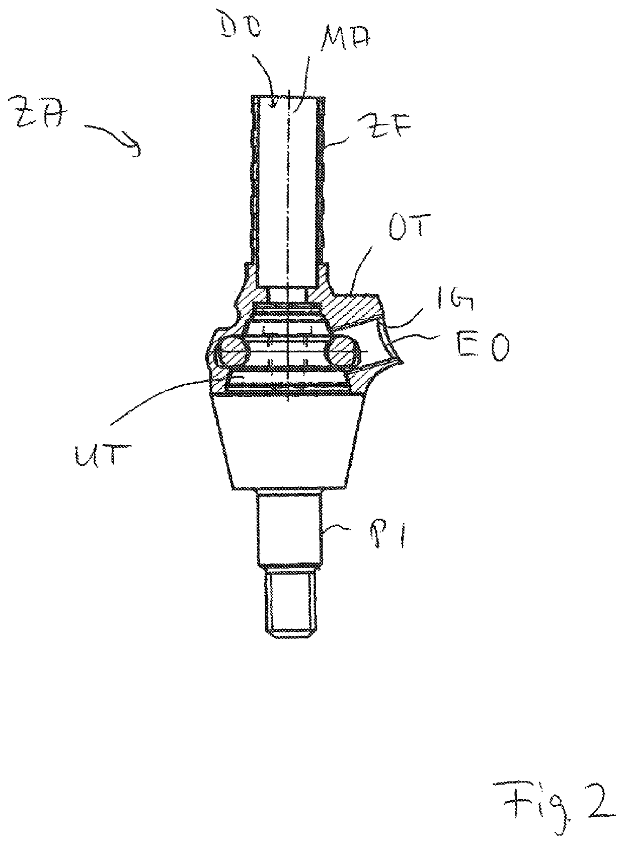
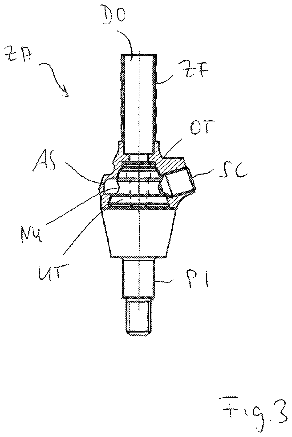
[0054]In FIG. 1, a first embodiment of the dental prosthesis arrangement ZA according to the invention is shown schematically in a side representation, partly in section. A lower part UT is applied to a jaw implant, indicated schematically with the reference symbol PI, which part is covered by an upper part OT. The upper part OT can be used as a superstructure body for a dental prosthesis not shown in FIG. 1. The upper part OT and the lower part UT together form a connection segment VA, so that the lower part assigned to the jaw implant PI and the upper part assigned to the superstructure are connected with one another. The lower part UT engages into the upper part OT along a center axis MA. The lower part UT is supported against the upper part OT at multiple contact surfaces AF. The lower part UT and the upper part OT are releasably connected with one a...


PUM


Abstract

A dental prosthesis arrangement includes a lower part assigned to a jaw implant and an upper part assigned to a superstructure. The lower part engages in the upper part along a central axis. The lower part is supported against the upper part at several contact faces. The lower part and the upper part are connected releasably to each other via a securing device which provides a retaining force against axial withdrawal of the upper part from the lower part. A first radially inwardly directed structure is provided on the lower part and a second radially outwardly directed structure is provided on the upper part for receiving a holding element that provides the retaining force. A fastener passing through the upper part and connected to the lower part can alternatively fix the upper part to the lower part.

Description

CROSS REFERENCE TO RELATED APPLICATIONS[0001]This application is the National Stage of PCT / EP2014 / 078054 filed on Dec. 16, 2014, which claims priority under 35 U.S.C. § 119 of German Application No. 10 2013 114 779.8 filed on Dec. 23, 2013, the disclosures of which are incorporated by reference. The international application under PCT article 21(2) was not published in English.BACKGROUND OF THE INVENTION1. Field of the Invention[0002]The invention relates to a dental prosthesis arrangement.2. Description of the Related Art[0003]It is known that dental prostheses are used to replace missing teeth of a set of teeth. In this regard, dental prosthesis arrangements are used that have a superstructure anchored in the jawbone by way of a jaw implant. It is advantageous that a cohesive superstructure can be provided by way of multiple jaw implants, for placement of multiple adjacent teeth or also all the teeth of a jaw.[0004]From the general state of the art, it is known to carry out attach...

Claims


Application Information

Patent Timeline
Patent Type & Authority Patents(United States)
IPC IPC(8): A61C8/00
CPCA61C8/0054A61C8/0066A61C8/0056A61C8/0068A61C8/0062A61C8/0057A61C13/2656
Inventor BREHM, PETER
Owner BREDENT
Learn More