Radiosonde air temperature measurement correction system and method

a technology of air temperature measurement and correction system, applied in the field of radiosonde, can solve the problems of inability to accurately measure temperature, unsatisfactory temperature rise, and relatively expensive pyrheliometer, and achieve the effect of high user precision and efficient correction of measured temperature valu

Active Publication Date: 2020-02-04
KOREA RES INST OF STANDARDS & SCI
View PDF12 Cites 0 Cited by
  • Summary
  • Abstract
  • Description
  • Claims
  • Application Information

AI Technical Summary

Benefits of technology

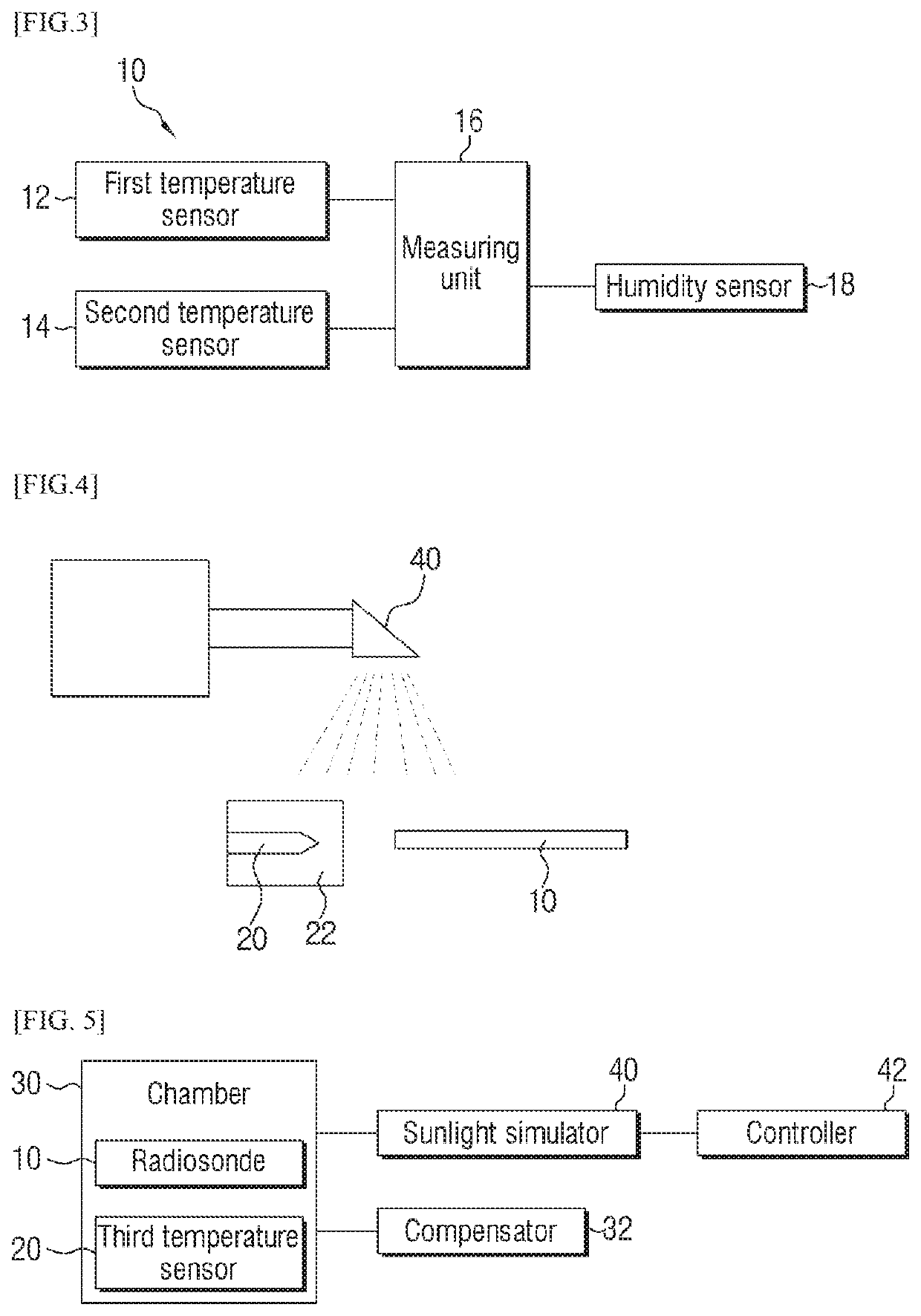
[0047]The present disclosure may provide to an apparatus embodied in order to efficiently correct changing of measured temperature value in a temperature sensor according to influence of irradiance.
[0048]Specifically, the present disclosure can provide the user an apparatus and a method of correcting temperature variation due to irradiance by mounting two temperature sensors of the same type that are coated with materials having different emissivity and using difference of temperature values measured by the two temperature sensors.
[0049]In addition, the present disclosure may provide an apparatus and a method that can compensate the influence of the irradiance regardless of the area, time, and weather condition by applying thereof after observing the temperature difference of the two temperature sensors to be occurred according to the irradiance in advance, and realize very high precision to users.

Problems solved by technology

In this process, undesirable temperature rises due to the irradiance may occur, but a method of correcting risen temperature due to the irradiance was not developed in the related art, so the temperature cannot be measured accurately.
In addition, the pyrheliometer is a relatively expensive instrument; therefore using the pyrheliometer is economically infeasible in an aspect of cost.

Method used


Image

  • Radiosonde air temperature measurement correction system and method
  • Radiosonde air temperature measurement correction system and method
  • Radiosonde air temperature measurement correction system and method

Examples


Embodiment Construction

[0074]Hereinafter, an exemplary embodiment of the present disclosure will be described in detail with reference to the accompanying drawings. In addition, an exemplary embodiment described in the following will not be construed as being limited to the detailed description of the present disclosure, and entire configuration described in the mode for the present disclosure are not deemed essential for solution of the present disclosure.

[0075]In addition, throughout the drawings, with reference to a description of relevant functions or action, like description of symbols will be used. Throughout the drawings, when an element is referred to ‘connect’ with other element, it can be ‘directed connect’ with other element of ‘indirectly connected’ in between other element may also be present.

[0076]Also, unless explicitly described to the contrary, the word “comprise” and variations such as “comprises” or “comprising” will be understood to imply the inclusion of stated elements but not the ex...


PUM

PropertyMeasurementUnit
air temperatureaaaaaaaaaa
temperatureaaaaaaaaaa
irradianceaaaaaaaaaa

Abstract

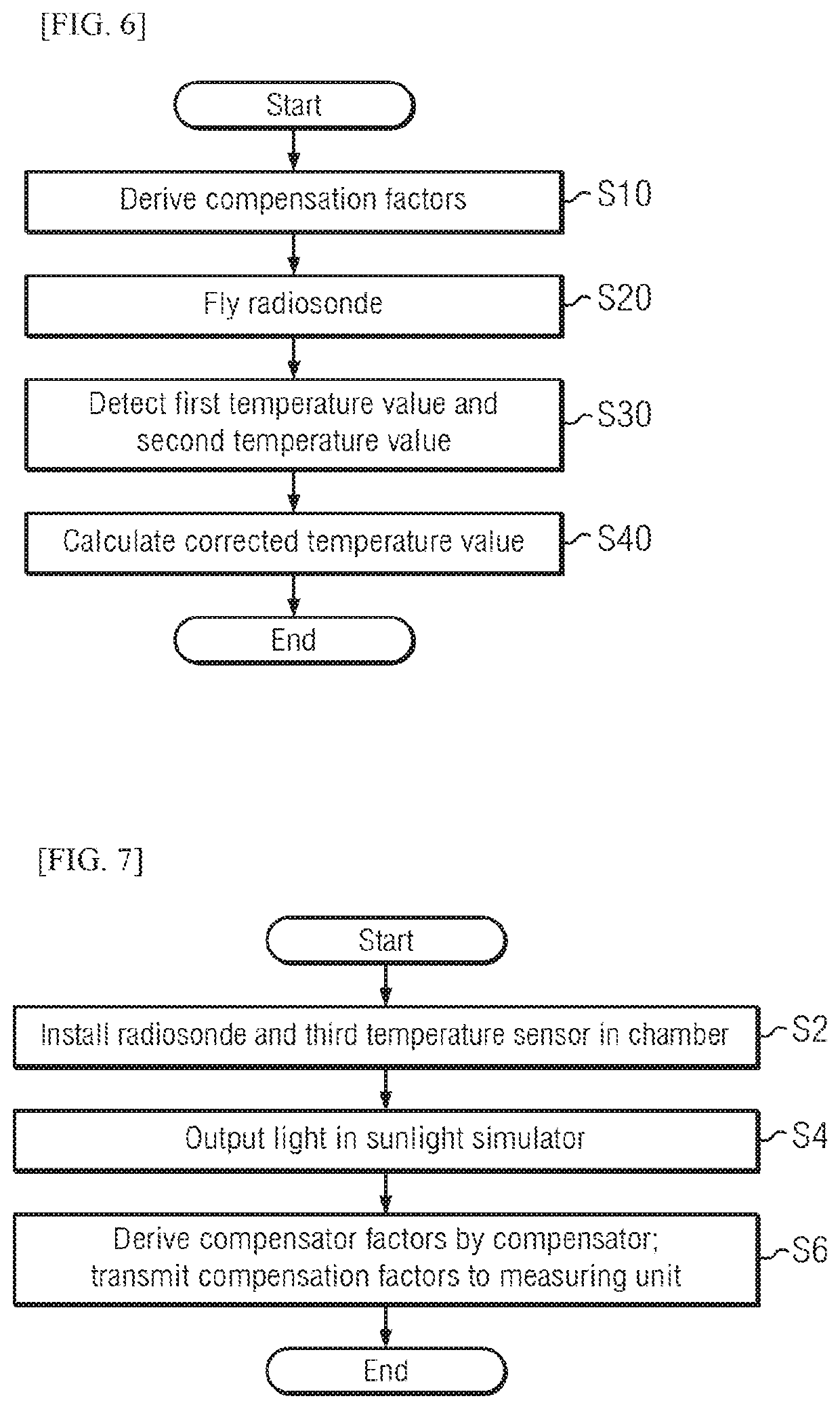
The present disclosure relates to an apparatus embodied in order to correct efficiently changing of measured temperature value in a temperature sensor according to influence of irradiance. A radiosonde related an exemplary embodiment of the present disclosure includes a first temperature sensor; a second temperature sensor having higher emission ratio than the first temperature sensor; and a measuring unit in order to calculate corrected temperature value, but the radiosonde and the third temperature sensor are installed in a chamber before flying of the radiosonde, a first temperature change detected by the first temperature sensor by output light in a sunlight simulator and a second temperature change detected by the second temperature sensor are induces, compensation factors may be derived using the first temperature change, the second temperature change, and temperature value measured by the third temperature sensor.

Description

TECHNICAL FIELD[0001]The present invention relates to a radiosonde furnished with multiple temperature sensors and, more particularly, relates to an apparatus and method embodied to allow variation due to the effect of radiation intensity on temperature values measured by the temperature sensors to be corrected efficiently.BACKGROUND ART[0002]The atmosphere surrounding a surface of the Earth has a great influence on human life. Among the observation apparatuses used for understanding the structure and change of the atmosphere, a radiosonde is the observation apparatus mounted with temperature, humidity, and GPS sensors which is suspended from a balloon and sent into the atmosphere, and which then understands the upper air condition by receiving observation data transmitted from the observation apparatus at a regular interval of time.[0003]The radiosonde measures directly the temperature, pressure, and humidity, etc., by flying in the atmosphere, and the wind is calculated by underst...

Claims


Application Information

Patent Timeline
Patent Type & Authority Patents(United States)
IPC IPC(8): G01W1/08G01W1/18G01K13/00G01K7/16G01J1/00G01W1/04G01K7/02G01J5/20G01J5/12G01J5/00
CPCG01W1/08G01J1/00G01K7/02G01J5/20G01W1/18G01J5/007G01K13/00G01W1/04G01K7/16G01J5/12G01J2005/0051G01J5/802G01K1/20G01K13/02G01K15/005
Inventor KIM, YONG-GYOOCHOI, BYUNG ILKIM, JONG CHEOLWOO, SANG BONGLEE, SANG WOOKKWON, SU YONG
Owner KOREA RES INST OF STANDARDS & SCI
Why Eureka
Try Eureka