
Blocking device and system for mechanical lock

a technology of blockage device and mechanical lock, which is applied in the direction of cylinder locks, building locks, construction, etc., can solve the problems of other locks failing to protect their coded locking system from manipulation and picking based attacks

Active Publication Date: 2020-02-18
VORNBROCK ANDRE JOHN
View PDF3 Cites 0 Cited by
  • Summary
  • Abstract
  • Description
  • Claims
  • Application Information

AI Technical Summary

Benefits of technology

The invention is a control device that makes it harder to turn a plug in a lock using a mechanical or magnetic key. The device includes a blocking mechanism that stops movement of the rotors, pins, or discs when the plug is turned. This prevents direct manipulation of the lock, and only an authorized key can open it. The technical effect of this innovation is an improved security measure to prevent unauthorized access to the lock.

Problems solved by technology

Other locks fail to protect their coded locking system from manipulation and picking based attacks.

Method used


Image

  • Blocking device and system for mechanical lock
  • Blocking device and system for mechanical lock
  • Blocking device and system for mechanical lock

Examples


Embodiment Construction

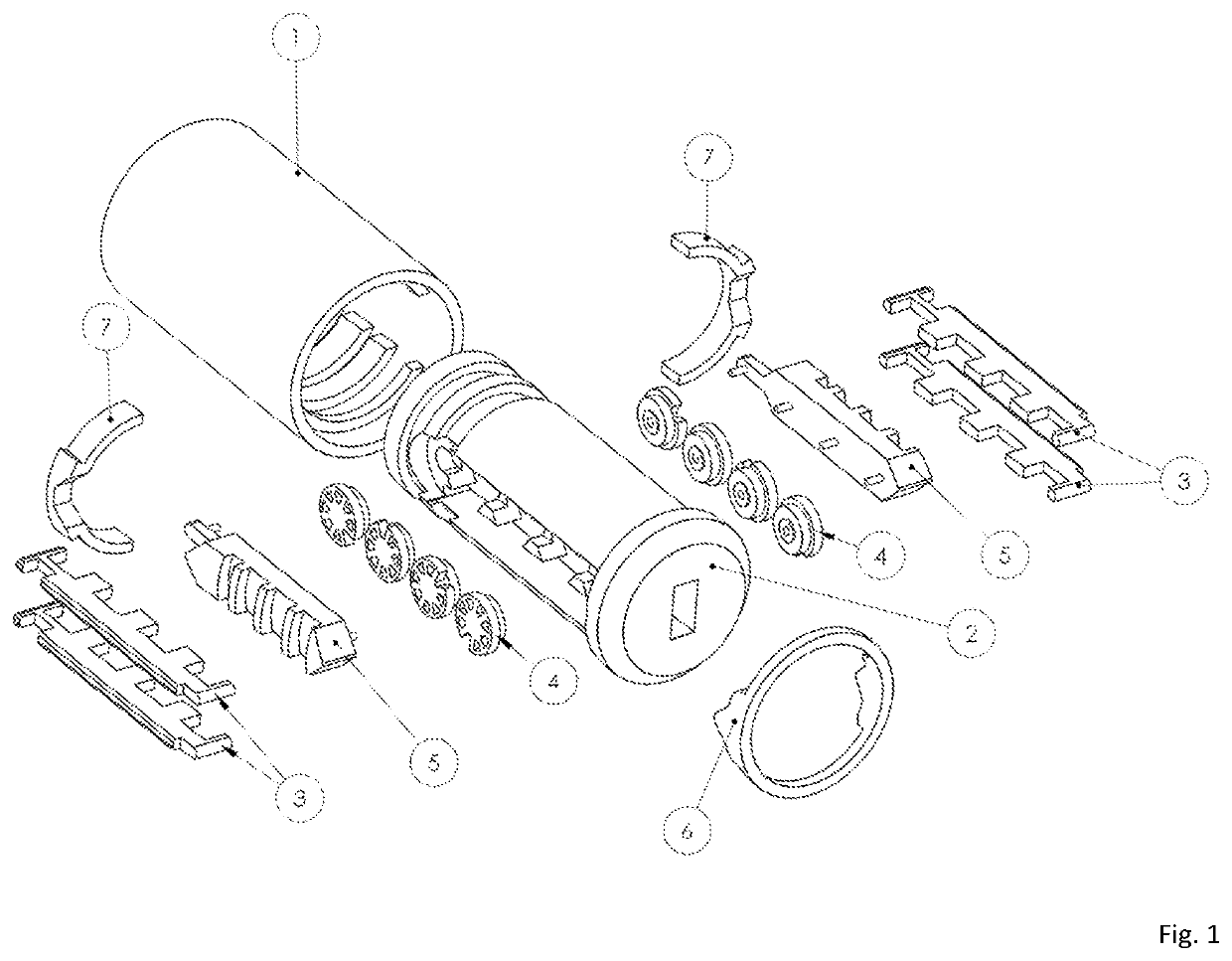
[0010]Referring now to the invention in more detail, FIG. 1 shows parts of a cylinder lock according to the invention. The control device of this invention includes a stationary housing 1 defining a cylindrical passage in which a cylindrical plug 2 is arranged for rotation about its center axis. Plug 2 defines a central key channel into which a magnetically coded key is insertable from the front.

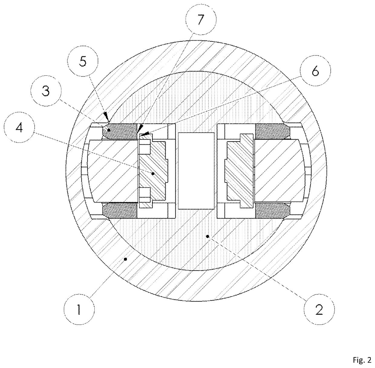
[0011]FIG. 2 shows a cross-sectional view from the front of the lock. Rotor blocking bar 3 is positioned so that when the core 2 is rotated respective to the housing 1 slightly, it will contact Point 5 and retract towards the center of the plug 2 until Point 7 touches rotary members 4 at point 6 preventing their movement entirely.

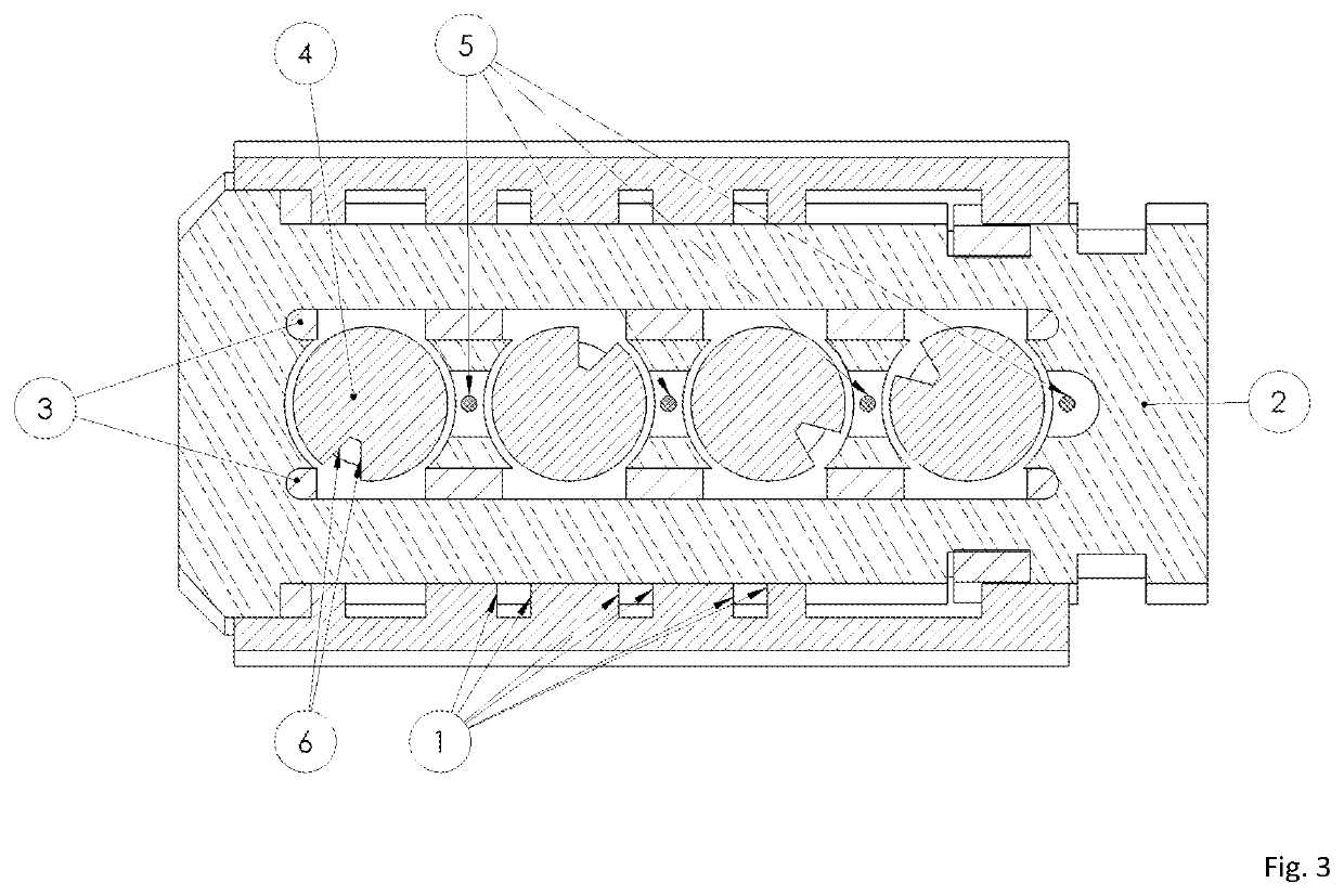
[0012]If rotation continues sidebar 2 in FIG. 4 will begin to travel up until pins 5 meet rotary members 4. If all pins 5 encounter correct gates 6 in FIG. 3, the sidebar 2 in FIG. 4 can continue travel forward until it is in the unlocked position. The unlocked posi...


PUM


Abstract

Blocking devices to stop movement of mechanical or magnetic coded rotors, pins or discs immediately when the plug is turned.

Description

BACKGROUND OF THE INVENTION[0001]This invention relates generally to an arresting control device and more particularly it relates to a control device for a mechanical or magnetic cylinder lock having a stationary cylindrical housing and a rotatable plug arranged in the housing with a specialized blocking system.[0002]Other locks fail to protect their coded locking system from manipulation and picking based attacks.SUMMARY OF THE INVENTION[0003]The primary object of this invention is to provide an improved control device which permits the actuation of the plug in a lock with a mechanical or magnetically coded key, whereby the decoding of the lock is rendered more difficult.[0004]In keeping with this object is the addition of a blocking device to stop movement of mechanical or magnetic coded rotors, pins or discs immediately when the plug is turned. This novel addition prevents direct manipulation of the rotors / pins / discs with the intention that the lock can only be opened by an autho...

Claims


Application Information

Patent Timeline
Patent Type & Authority Patents(United States)
IPC IPC(8): E05B47/00E05B17/04E05B27/00
CPCE05B47/0044E05B17/047E05B47/0042E05B27/0021E05B27/006
Inventor VORNBROCK, ANDRE JOHN
Owner VORNBROCK ANDRE JOHN
Learn More