Computer user authentication system

Inactive Publication Date: 2007-12-20
HMI
View PDF2 Cites 3 Cited by
  • Summary
  • Abstract
  • Description
  • Claims
  • Application Information

AI Technical Summary

Benefits of technology

[0011]In another technical means of the present invention for solving the problem, the controller of the computer includes a locking unit for making the computer unusable when the authentication key connected to the interface of the computer i

Problems solved by technology

As a result, there is a possibility that the password (encryption c

Method used


Image

  • Computer user authentication system
  • Computer user authentication system
  • Computer user authentication system

Examples


Embodiment Construction

[0019]Hereinafter, an embodiment of the present invention will be described referring to figures.

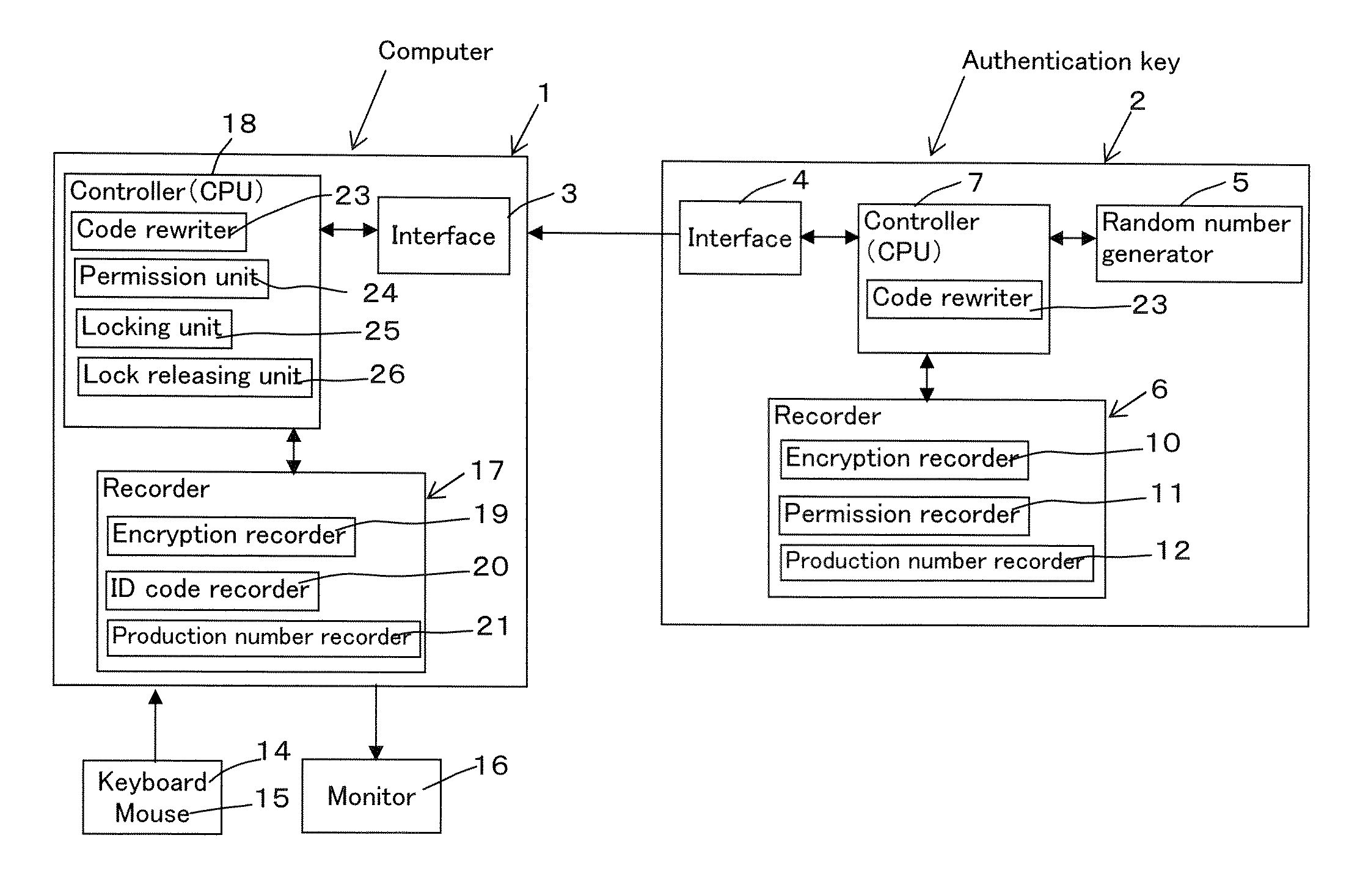
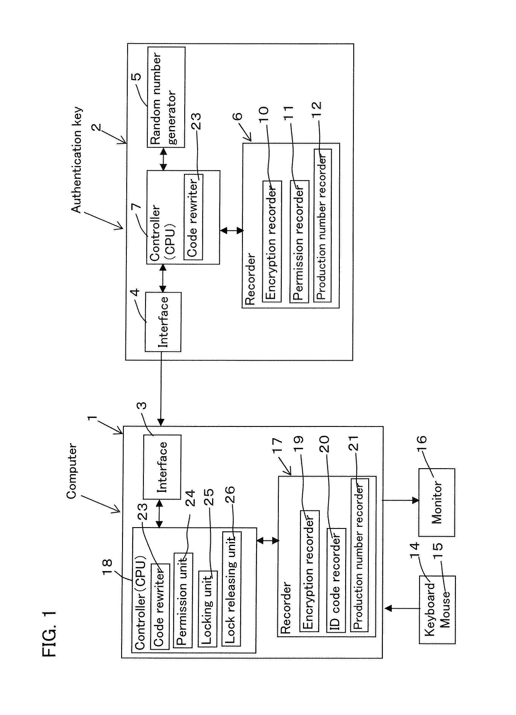
[0020]As shown in FIG. 1, a computer user authentication system has a computer 1 and an authentication key 2 for authorizing the use of the computer 1.

[0021]The authentication key 2 can be connected to an interface 3 (for example, an USB interface) of the computer 1 and has an interface 4 that can be connected to the interface 3, a random number generator 5, a recorder 6 (storage) and a controller 7 (CPU) that can control the user authentication system.

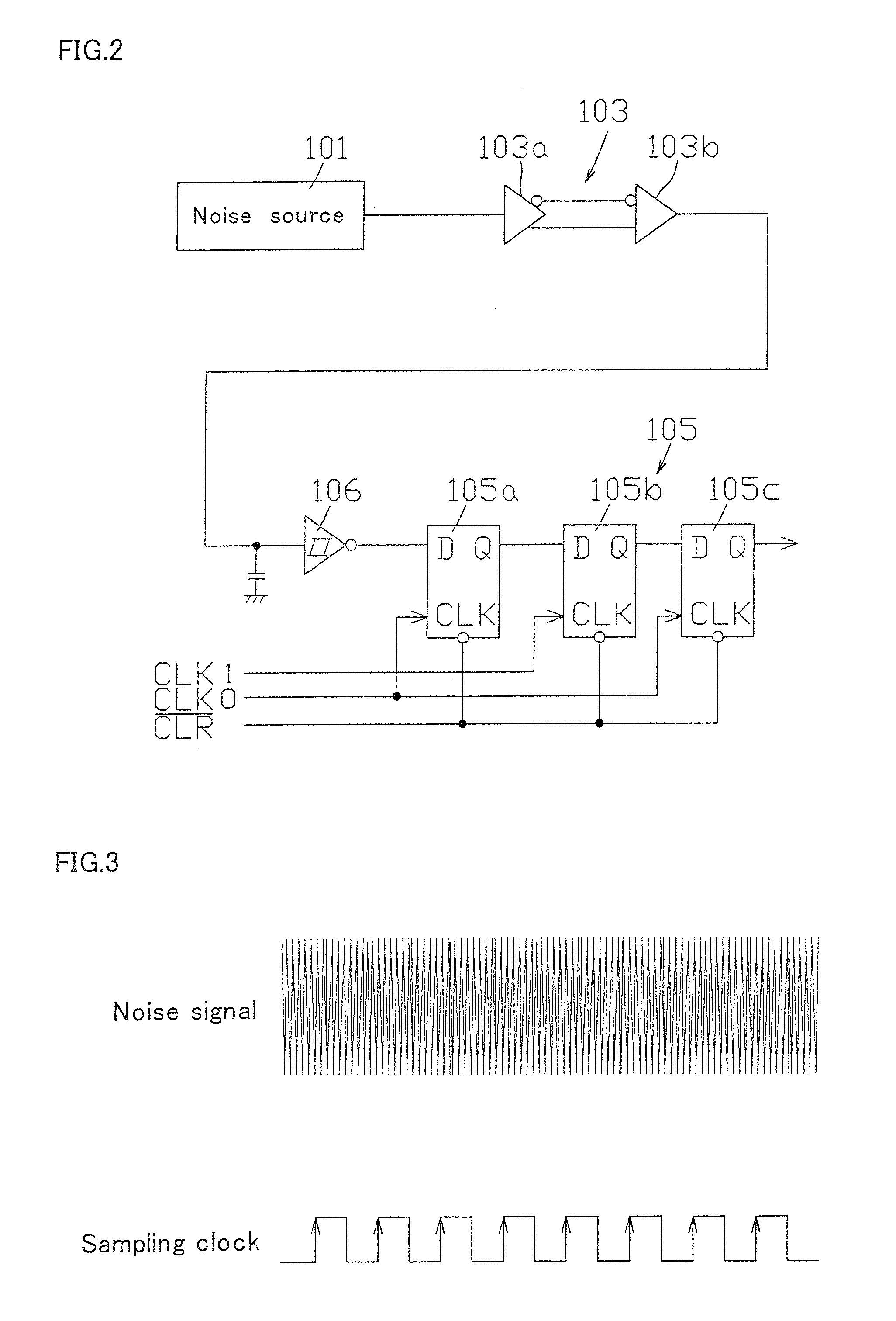
[0022]The random number generator 5, as shown in FIGS. 1 and 2, has a noise source 101 for outputting a noise signal, an amplifier 103 for amplifying the noise signal output from the noise source 101 and a binarization device 105 for binarizing the amplified noise signal.

[0023]The noise source 101 uses thermal noise of a semiconductor as noise and compared to the use of pseudorandom numbers, the use of the thermal noise of the semiconducto...


PUM


Abstract

A computer authentication system is provided with a random number generator 5 for generating a random number on the basis of a noise signal generated by a noise generator and a code rewriter for creating a new encryption code on the basis of the random number generated by the random number generator 5 when the encryption code of a computer 1 corresponds to the encryption code of an authentication key 2, rewriting the encryption code recorded in a encryption recorder 19 of the computer 1 to the new encryption code and rewriting the encryption code recorded in an encryption recorder 10 of the authentication key 2 to the new encryption code.

Description

BACKGROUND OF THE INVENTION[0001]The present invention relates to a user authentication system that can permit the use of a computer when an authentication key is attached to the computer.[0002]Conventionally, a user authentication system has been known in which by inserting an authentication key (IC card) into a computer (terminal device) and inputting a password to the computer, the password of the computer is collated with the password of the authentication key through predetermined processing and when these passwords correspond to each other, the use of the computer is permitted. This type of user authentication system is disclosed in, for example, Japanese Unexamined Patent Publication No. 1993-290225.[0003]In the user authentication system, in inserting the authentication key into the computer, a pseudorandom number is generated on the side of the authentication key and the password is encrypted on the side of the computer using the pseudorandom number. Furthermore, in the use...

Claims


Application Information

Patent Timeline
IPC IPC(8): G06F17/30H04L9/00G06F7/04G06K9/00H03M1/68H04K1/00H04L9/32H04N7/16
CPCG06F21/305G06F21/31G06F2221/2129G06F2221/2103G06F2221/2107G06F21/72
Inventor IKAKE, KATSUNORI
Owner HMI
Why Eureka
Try Eureka