Photoacoustic measurement device and puncture needle

a technology of photoacoustic measurement and puncture needle, which is applied in the direction of instruments, applications, ultrasonic/sonic/infrasonic image/data processing, etc., can solve the problems of difficult to confirm the position of the puncture needle by using a photoacoustic image, and light applied from the surface of the subject does not sufficiently reach the puncture needl

Active Publication Date: 2020-02-25
FUJIFILM CORP
View PDF18 Cites 2 Cited by
  • Summary
  • Abstract
  • Description
  • Claims
  • Application Information

AI Technical Summary

Benefits of technology

The invention has been made in consideration of the above-mentioned problems, and an object of the invention is to provide a photoacoustic image generating device that can confirm the position of a puncture needle in a photoacoustic image even in the case where the puncture needle is stuck to a deep position from the surface of a subject.
In the photoacoustic image generating device of the invention, the puncture needle is provided with the light guide that extends in the longitudinal direction of the hollow puncture needle body and emits light at least in part to the hollow puncture needle body while guiding light emitted from the light source toward the tip of the hollow puncture needle body. In the invention, light is emitted to the hollow puncture needle body from the light guide in the longitudinal direction of the puncture needle and photoacoustic waves are generated from a portion, to which light is irradiated, of the hollow puncture needle body. Since the puncture needle is provided with the light guide that emits light, photoacoustic waves can be generated at the puncture needle even when the puncture needle is stuck to a deep position from the surface of a subject. Since a photoacoustic image is generated on the basis of detected photoacoustic waves, it is possible to confirm the position of the puncture needle.

Problems solved by technology

Particularly, when a tip of a puncture needle is stuck to a deep position, light applied from the surface of the subject does not sufficiently reach the puncture needle that is stuck to the deep position.
For this reason, it is difficult to confirm the position of the puncture needle by using a photoacoustic image.
For this reason, there is a case in which it is difficult to confirm the position of the needle.

Method used


Image

  • Photoacoustic measurement device and puncture needle
  • Photoacoustic measurement device and puncture needle
  • Photoacoustic measurement device and puncture needle

Examples


first embodiment

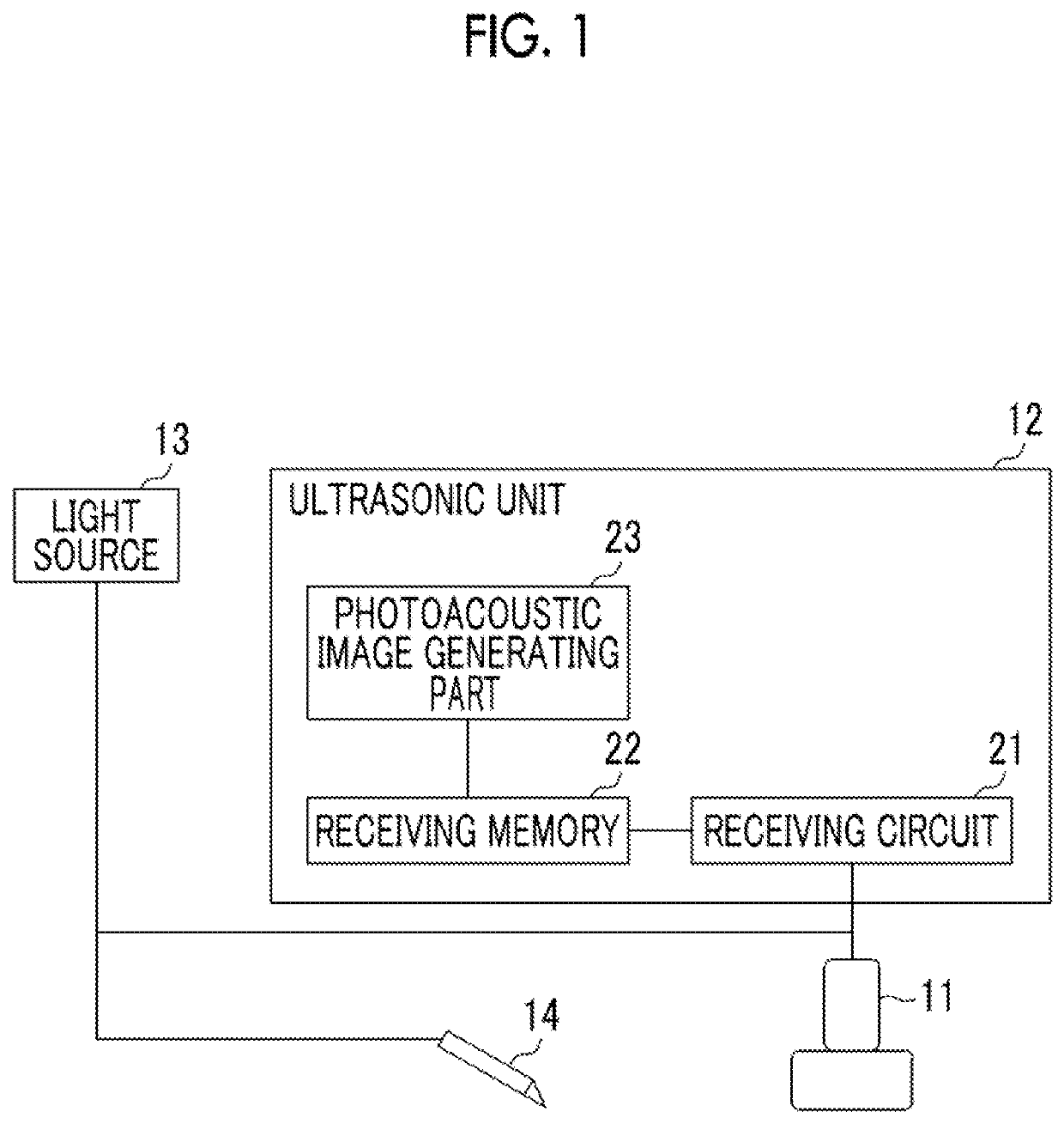
Embodiments of the invention will be described below in detail with reference to the drawings. FIG. 1 shows a photoacoustic image generating device according to the invention. The photoacoustic image generating device 10 includes a probe (ultrasonic probe) 11, an ultrasonic unit 12, and a light source unit 13. Meanwhile, an ultrasonic wave is used as an acoustic wave in the embodiment of the invention, but the acoustic wave is not limited to the ultrasonic wave. As long as an appropriate frequency is selected according to a subject, measurement conditions, or the like, an acoustic wave having an audio frequency may be used.

The light source unit (light source) 13 is formed of, for example, a laser light source. The light source unit 13 includes a solid-state laser using, for example, YAG (yttrium.aluminum.garnet), alexandrite, or the like. Laser light emitted from the light source unit 13 is guided to a puncture needle 14 by light guide means such as an optical fiber. Further, laser ...

second embodiment

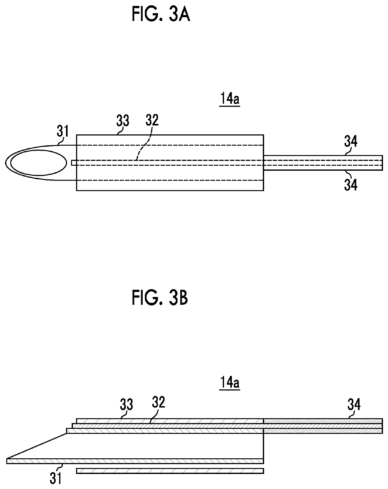
In this embodiment, the clad 34 of the optical fiber, which guides light emitted from the light source unit 13 to the puncture needle 14b, is removed at a plurality of locations, so that a plurality of exposed portions 35 are formed in the longitudinal direction of the puncture needle 14b. A part of light, which travels through the light guide 32 toward the tip of the puncture needle 14b, leaks from the exposed portions 35 and is emitted to the puncture needle body 31. Since light is discretely irradiated to the puncture needle body 31 in this embodiment, photoacoustic waves can be discretely generated in the longitudinal direction of the puncture needle 14b. Other effects are the same as those of the

Subsequently, a fourth embodiment of the invention will be described. FIG. 5A is a top view of a puncture needle used in the fourth embodiment of the invention and FIG. 5B is a sectional view of a central portion of the puncture needle. The fourth embodiment is different from the first ...

seventh embodiment

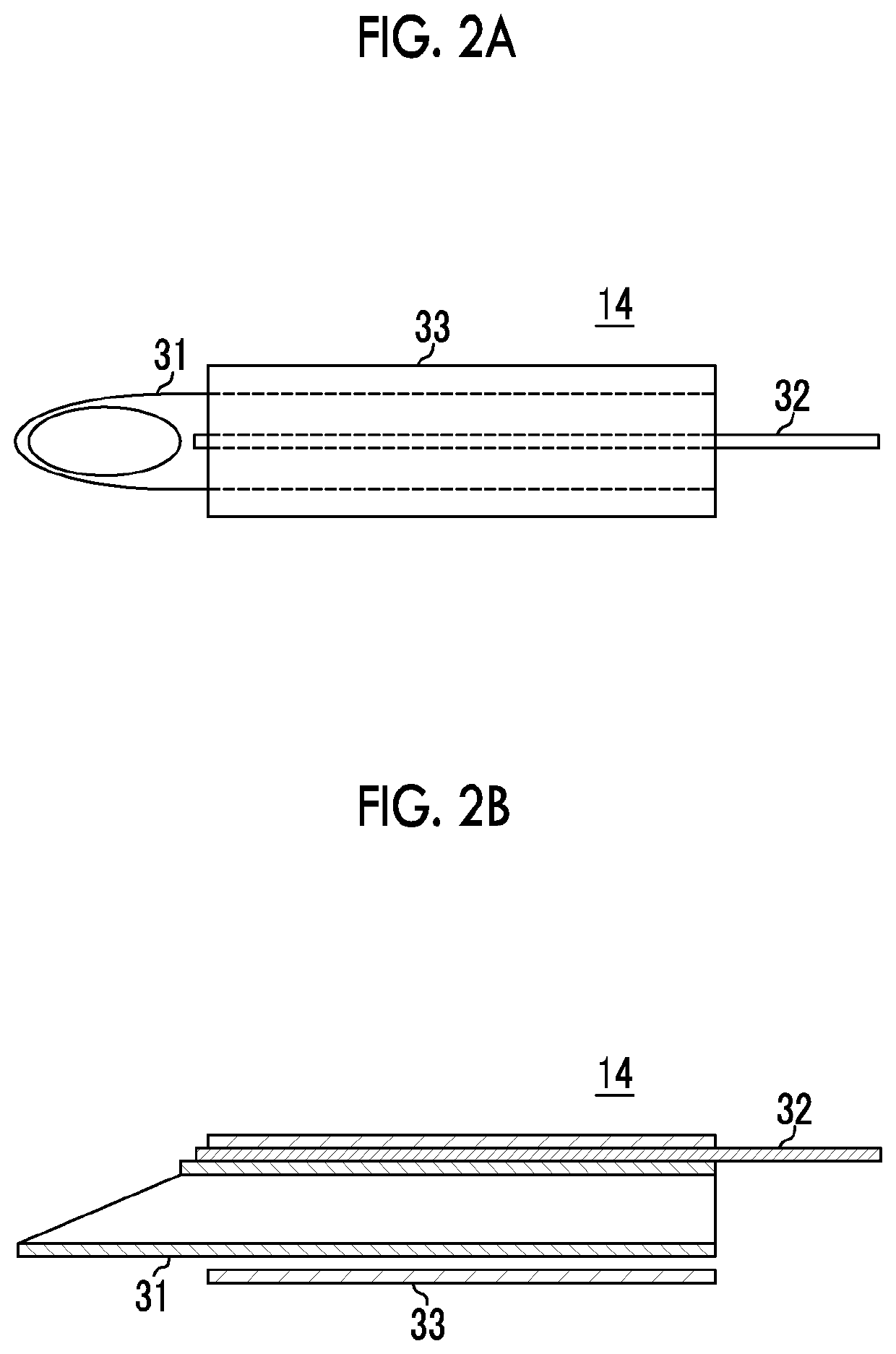
An example in which end face treatment is not performed at the tip portion of the light guide 32 has been described in each of the above-mentioned embodiments, but any end face treatment can be performed at the tip portion. For example, in FIG. 2B, the tip of the light guide 32 and the tip of the puncture needle 14 may be obliquely cut at the same angle and in the same direction. In this case, since light emitted from the tip of the light guide is directed to the puncture needle body 31, photoacoustic signals generated from the tip portion can be strengthened. In the case where the light guide 32 is disposed in the puncture needle body 31 as in the seventh embodiment, the end of the light guide 32 and the end of the puncture needle 14 need to be cut in a direction opposite to the direction of the case in which the light guide 32 is disposed outside the puncture needle body 31.


PUM

PropertyMeasurementUnit
photoacousticaaaaaaaaaa
photoacoustic waveaaaaaaaaaa
photoacoustic measurementaaaaaaaaaa

Abstract

A photoacoustic measurement device having a puncture needle, where the puncture needle 14 is a hollow needle that has an opening formed at a tip thereof. The puncture needle 14 includes a puncture needle body 31 and a light guide 32. The light guide 32 extends in a longitudinal direction of the puncture needle body. The light guide 32 emits light at least in part to the puncture needle body 31 while guiding light emitted from a light source toward the tip of the puncture needle body.

Description

BACKGROUND OF THE INVENTION1. Field of the InventionThe present invention relates to a photoacoustic measurement device, and more particularly, to a photoacoustic image generating device that generates a photoacoustic image on the basis of photoacoustic waves generated due to the emission of light after light is emitted to a subject. Further, the invention relates to a puncture needle that is used for the photoacoustic image generating device.2. Description of the Related ArtAn ultrasonic inspection method is known as one kind of image inspecting method that can inspect the internal state of a living body in a non-invasive manner. An ultrasonic probe, which can transmit and receive ultrasonic waves, is used for ultrasonic inspection. When ultrasonic waves are transmitted to a subject (living body) from the ultrasonic probe, the ultrasonic waves travel in the living body and are reflected by a tissue interface. When a distance is calculated on the basis of a time until the reflected ...

Claims


Application Information

Patent Timeline
Patent Type & Authority Patents(United States)
IPC IPC(8): A61B8/08A61B17/34A61B5/00A61B90/30A61B90/00A61B5/06G01N21/17G01N29/24
CPCA61B17/3403A61B8/0841A61B5/061G01N2201/106G01N21/1702A61B5/0095A61B2090/3945G01N2201/067G01N29/2418A61B5/6848A61B2090/306
Inventor IRISAWA, KAKUTSUJITA, KAZUHIRO
Owner FUJIFILM CORP
Why Eureka
Try Eureka