
Photoacoustic image generating device and insertion object

a technology of photoacoustic image and generating device, which is applied in the direction of diagnostic recording/measuring, applications, and applications, etc., can solve the problems of difficult to confirm the position of the puncture needle tip in the photoacoustic image, and the depth of the insertion position of the puncture needle is not sufficiently reached by the light applied on the surface of the subject, etc., to achieve the effect of confirmating the position of the insertion obj

Active Publication Date: 2020-08-06
FUJIFILM CORP
View PDF0 Cites 0 Cited by
  • Summary
  • Abstract
  • Description
  • Claims
  • Application Information

AI Technical Summary

Benefits of technology

[0007]The invention has been made in consideration of the above-mentioned problems, and an object of the invention is to provide a photoacoustic image generating device that can confirm the position of an insertion object in a photoacoustic image even when the insertion object is inserted to a deep position from the surface of a subject or even when the insertion object is inserted into the subject at an angle close to a right angle.
[0040]In the photoacoustic image generating device of the invention, it is possible to confirm the position of an insertion object in a photoacoustic image even when an insertion object is inserted to a deep position from the surface of a subject or even when the insertion object is inserted into the subject at an angle close to a right angle.

Problems solved by technology

For this reason, particularly, when the tip of the puncture needle is inserted to a deep position (for example, a position at a depth from the surface of the subject of a distance of 3 cm), light applied on the surface of the subject does not sufficiently reach the puncture needle inserted to the deep position.
Accordingly, it is difficult to confirm the position of the tip of the puncture needle in the photoacoustic image.
For this reason, there is also a problem in that it is difficult to detect photoacoustic waves generated from the puncture needle.
In other words, there is also a problem in that it is more difficult to confirm the position of the puncture needle in the photoacoustic image as a insertion angle approaches a right angle.
These problems are not limited to the puncture needle, and may be generated when the position of an insertion object to be inserted into a subject is to be confirmed using a photoacoustic image.

Method used


Image

  • Photoacoustic image generating device and insertion object
  • Photoacoustic image generating device and insertion object
  • Photoacoustic image generating device and insertion object

Examples


first embodiment

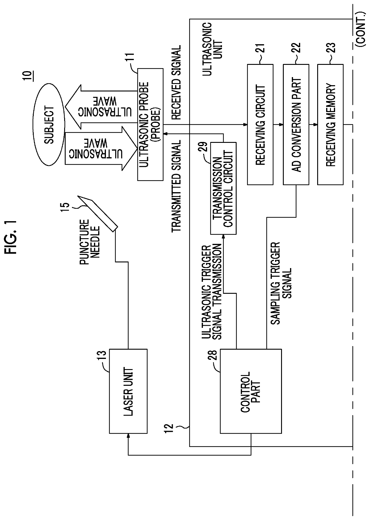
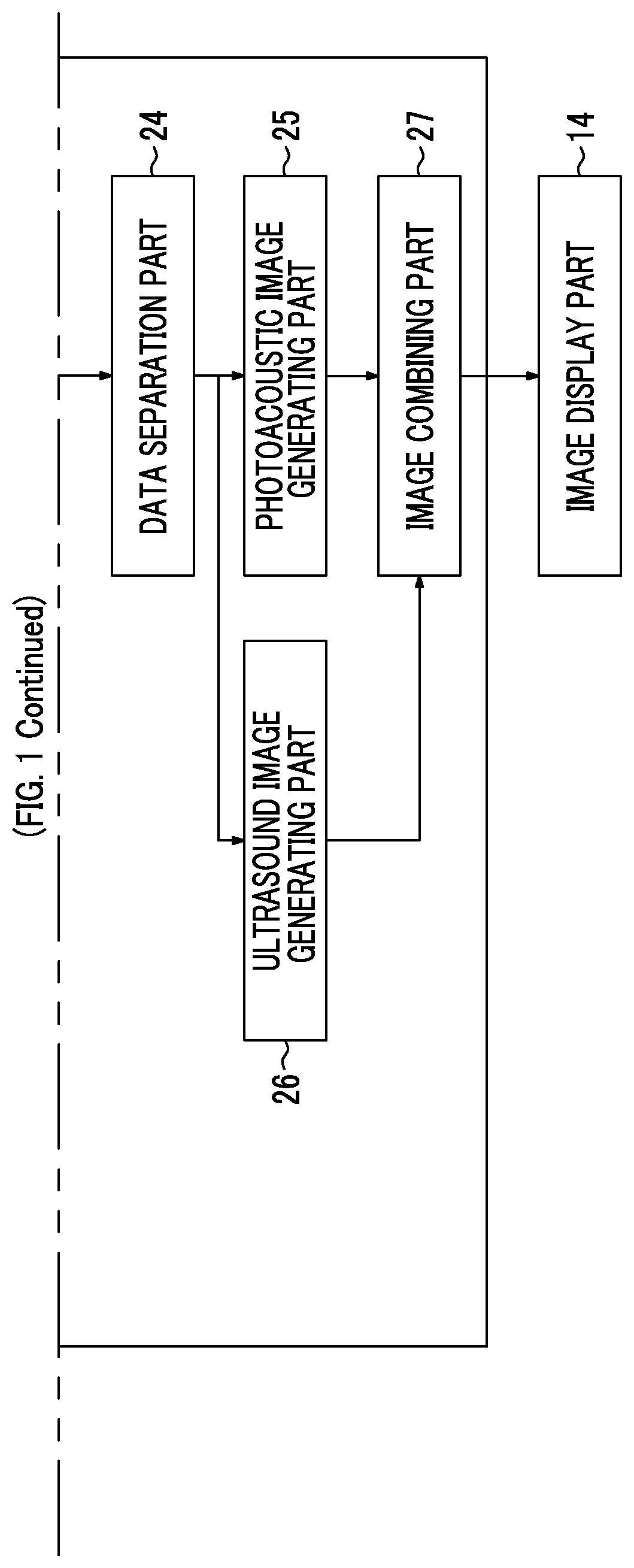
[0072]Embodiments of the invention will be described in detail below with reference to the drawings. FIG. 1 illustrates a photoacoustic image generating device according to the invention. The photoacoustic image generating device (photoacoustic image diagnostic device) 10 includes a probe (ultrasonic probe) 11, an ultrasonic unit 12, and a laser unit 13. Meanwhile, ultrasonic waves are used as acoustic waves in the embodiment of the invention, but the acoustic waves are not limited to the ultrasonic waves. As long as an appropriate frequency is selected according to a subject, measurement conditions, or the like, an acoustic wave having an audio frequency may be used.

[0073]The laser unit 13 is a first light source. The laser unit 13 is formed of a solid-state laser light source using, for example, YAG (yttrium aluminum garnet), alexandrite, or the like. In this embodiment, a puncture needle, which is inserted into a subject, is considered as an insertion object of which at least a t...

second embodiment

[0104]The light absorbent member 155, which is also a fixing member, is made of, for example, an epoxy resin, a polyurethane resin, a fluorine resin, silicone rubber, or the like into which a black pigment is mixed. The light absorbent member 155 covers a light emitting end of an optical fiber that is, for example, the light guide member 152 and fixes the end face of the optical fiber to the inner wall of a puncture needle body 151. Accordingly, it is possible to fix the light guide member 152, and to accurately ascertain a positional relationship between the tip of the puncture needle 15b and the tip (light emitting portion) of the light guide member 152. Other effects are the same as those of the

[0105]Next, a fourth embodiment of the invention will be described. FIG. 9 illustrates the section of a puncture needle that is used in a photoacoustic image generating device according to the fourth embodiment of the invention. This embodiment is different from the first embodiment in tha...

third embodiment

[0156]Since the refractive index of water, air, or the like present in the puncture needle 15 is lower than the refractive index of the optical fiber in the third embodiment, the light emitting end face of the optical fiber is formed obliquely so that a portion of the puncture needle close to the inner wall (a portion opposite to the center of the puncture needle) is long. When the puncture needle is filled with a material having a refractive index higher than the refractive index of the optical fiber, the end face of the optical fiber close to the light emitting end may be formed obliquely so that a portion of the puncture needle close to the center (a portion opposite to the inner wall) is long in contrast to FIG. 9.

[0157]The laser unit 13 and the laser unit 16 have been described as independent light sources in the fifth embodiment, but one light source may also function as the other light source. FIG. 21 illustrates a modification of light sources of first and second light sourc...


PUM


Abstract

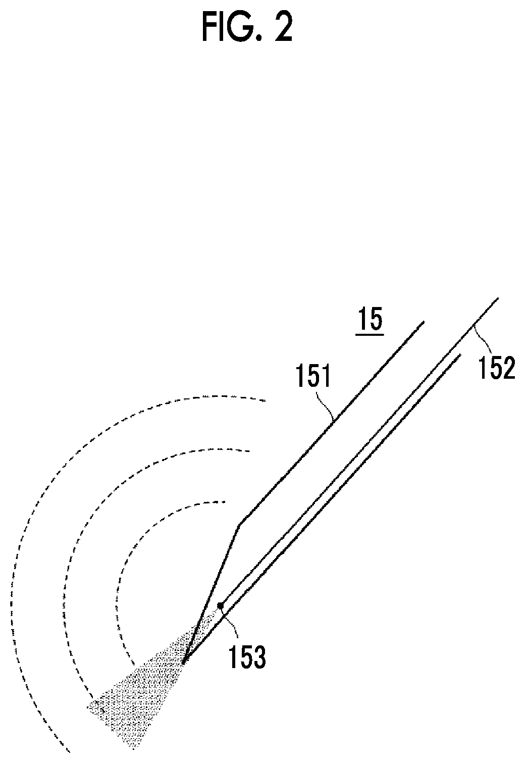
Even when an insertion object is inserted to a deep position of a subject or even when the insertion object is inserted into the subject at an angle close to a right angle, it is possible to confirm the position of the insertion object in a photoacoustic image. The insertion object is, for example, a hollow puncture needle 15 that includes an opening at a tip thereof. The puncture needle 15 includes a light guide member 152 that guides light emitted from a first light source to the vicinity of the opening, and a light emitting portion 153 that is provided in the vicinity of the opening and emits the light. First photoacoustic waves, which are caused. by the light emitted from the light emitting portion 153, are generated in the puncture needle 15. A first photoacoustic image is generated on the basis of the first photoacoustic waves.

Description

CROSS-REFERENCE TO RELATED APPLICATIONS[0001]This application is a Divisional of U.S. application Ser. No. 14 / 755,766 filed on Jun. 30, 2015, which is a Continuation of PCT International Application No. PCT / JP2013 / 082617 filed on Dec. 4, 2013, which claims priority under 35 U.S.C. § 119(a) to Japanese Patent Application No. 2013-001519 filed on Jan. 9, 2013, Japanese Patent Application No. 2013-149497 filed on Jul. 18, 2013 and Japanese Patent Application No. 2013-247739 filed on Nov. 29, 2013. Each of the above applications is hereby expressly incorporated by reference, in its entirety, into the present application.BACKGROUND OF THE INVENTION1. Field of the Invention[0002]The present invention relates to a photoacoustic image generating device that generates a photoacoustic image on the basis of photoacoustic waves generated due to the irradiation of light. Further, the present invention relates to an insertion object which is used in the photoacoustic image generating device and o...

Claims


Application Information

Patent Timeline
Patent Type & Authority Applications(United States)
IPC IPC(8): A61B5/00A61B90/13A61B10/02A61B17/34A61B5/06A61B8/00A61B8/12A61B18/14
CPCA61B10/02A61B5/06A61B8/12A61B8/4281A61B5/6848A61B10/0283A61B5/6851A61B18/1477A61B5/0095A61B90/13A61B17/3403A61B2018/00595A61B2017/3413A61B5/061A61B5/6852A61B2090/3929A61B2090/397
Inventor IRISAWA, KAKU
Owner FUJIFILM CORP
Learn More