Industrial machinery and control method thereof

a technology of industrial machinery and control methods, applied in the direction of computer control, program control, instruments, etc., can solve the problems of inability to detect tool failure accurately with the torque of the main shaft, bulky and expensive industrial machinery, and difficulty in detecting tool failures

Active Publication Date: 2020-02-25
TOSHIBA MASCH CO LTD
View PDF4 Cites 0 Cited by
  • Summary
  • Abstract
  • Description
  • Claims
  • Application Information

AI Technical Summary

Benefits of technology

Accordingly, it is the purpose of the present invention, in order to solve the above problems, to provide an industrial machinery and a method of controlling the same, capable of easily and accurately detecting the tool failure.

Problems solved by technology

However, for example, if the main shaft torque is small, it is difficult to detect tool failure accurately with the main shaft torque.
However, in this case, the sensor is additionally required, resulting in a bulky and expensive industrial machinery.
Another problem is that, once the sensor is in failure, the tool failure cannot be detected.

Method used


Image

  • Industrial machinery and control method thereof
  • Industrial machinery and control method thereof
  • Industrial machinery and control method thereof

Examples


first embodiment

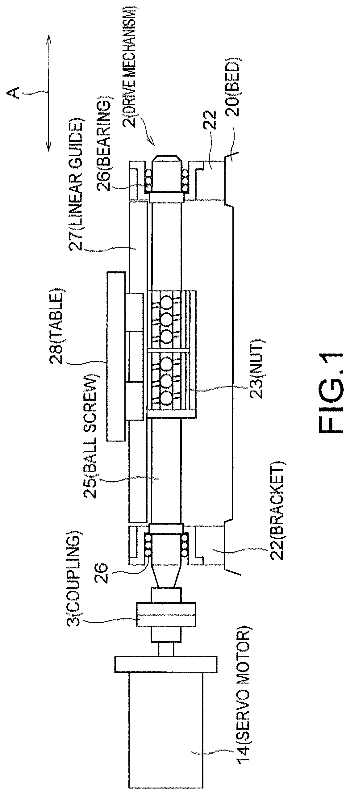
FIG. 1 is a diagram showing an example of the configuration of a servo motor 14 and a drive mechanism 2 of an industrial machinery according to a first embodiment. The servo motor 14 is coupled with the drive mechanism 2 via a coupling 3. The drive mechanism 2 is provided with a bed 20, brackets 22, a nut 23, a ball screw 25, bearings 26, a linear guide 27, and a table 28.

The bed 20 is fixed to a main frame of the industrial machinery. On the bed 20, the other components of the drive mechanism 2 are mounted. The brackets 22 are fixed on the bed 20 to support the ball screw 25 on both sides via the bearings 26. The ball screw 25 is coupled with the servo motor 14 via the coupling 3 so as to rotate with the rotation of a shaft of the servo motor 14. The nut 23 has a screw hole to be engaged with a screw portion of the ball screw 25. The nut 23 can move in an axial direction of the ball screw 25, as the ball screw 25 rotates. The table 28 as a control target is fixed to the nut 23 and ...

second embodiment

FIG. 8 is a graph showing an example of a tool failure determination method according to a second embodiment, the ordinate showing cutting force including the second component and the first component, and the abscissa showing time. It is a precondition that the drive mechanism 2 has a horizontal axis, with zero (N(Newton)) set at the origin Fcenter of the cutting force. In the case where the drive mechanism 2 has the axis of gravity, the origin Fcenter may be offset, as explained with reference to FIGS. 4A and 4B. Thus, the explanation of the case with the axis of gravity is omitted here.

For example, a tool having at least one blade, such as an end mill, cuts the same part of work by the number of blades per rotation. When the number of blades is M and the rotation speed at which the tool rotates is N (times of rotation / min), the second component of the cutting force has a waveform with a frequency of P=M×N / 60 (Hz) during processing, as explained above. Therefore, the error detector...

third embodiment

In the first and second embodiments, the NC apparatus 4 performs tool failure detection using the first component of the cutting force. Different from this, in the third embodiment, the NC apparatus 4 performs tool failure detection using the second component of the cutting force. The cutting force may be calculated in the same manner as explained in the first or second embodiment.

The second component of the cutting force will be explained. If any one of the tool blades is chipped way or worn away, there is a bigger change in the second component than in the first component, in the cutting force. For example, if the tool has many blades and, if one of the blades is chipped way, although there is a small change in the cutting force of the entire tool, there is a big change in the cutting force of the chipped blade. In this case, it is preferable for the NC apparatus 4 to use the second component that represents each blade cutting force, for tool failure detection. Therefore, the NC a...


PUM


Abstract

An industrial machinery includes: a drive mechanism driving a control target that moves work or a tool; a motor; a first sensor detecting a position of the control target; a second sensor detecting a position of the motor; a current controller controlling a supply current to the motor; a servo controller outputting a torque instruction to the current controller; and a numerical controller calculating a processing force of the control target to the work based on position information on the control target acquired from the first sensor, position information on the motor acquired from the second sensor, and the torque instruction, the numerical controller determining that the tool is in failure if an absolute value of a first component of the processing force becomes equal to or larger than a first threshold value while processing the work, the first component having a frequency lower than a predetermined frequency.

Description

CROSS REFERENCE TO RELATED APPLICATIONSThis application is based upon and claims the benefit of priority from the prior Japanese Patent Application No. 2016-223272, filed on Nov. 16, 2016, the entire contents of which are incorporated herein by reference.BACKGROUND OF THE INVENTIONField of the InventionThe embodiments of the present invention relate to an industrial machinery and control method thereof.Related ArtAn industrial machinery machines work with, for example, a tool attached to a main shaft. A numerical controlling apparatus (hereinafter, also referred to as an NC (Numerical Controller) apparatus) of the industrial machinery outputs an instruction to the main shaft to control an operation of the main shaft and monitors the main shaft torque, or a motor load current. The NC apparatus monitors the main shaft torque to detect failure of the tool used in work processing.However, for example, if the main shaft torque is small, it is difficult to detect tool failure accurately w...

Claims


Application Information

Patent Timeline
Patent Type & Authority Patents(United States)
IPC IPC(8): G05B19/402
CPCG05B19/402G05B2219/50297G05B2219/41112G05B19/4065G05B2219/34393G05B2219/37228G05B2219/37087
Inventor ITO, TAKAMICHIFUJITA, JUNTADA, ATSUSHIMATSUZAKI, HIROHIKO
Owner TOSHIBA MASCH CO LTD
Why Eureka
Try Eureka