
Automated system and method for lumber analysis

a technology of automatic system and lumber analysis, applied in the field of workpiece assembly devices and methods, can solve the problems of increasing the cost of labor when manufacturing structures using wood boards (lumber), and the inability of conventional automated or partially automated systems to determine and/or distinguish the crown of lumber, so as to reduce the footprint of the overall system, reduce costs, and save labor

Active Publication Date: 2020-03-03
WEIN HLDG LLC
View PDF57 Cites 5 Cited by
  • Summary
  • Abstract
  • Description
  • Claims
  • Application Information

AI Technical Summary

Benefits of technology

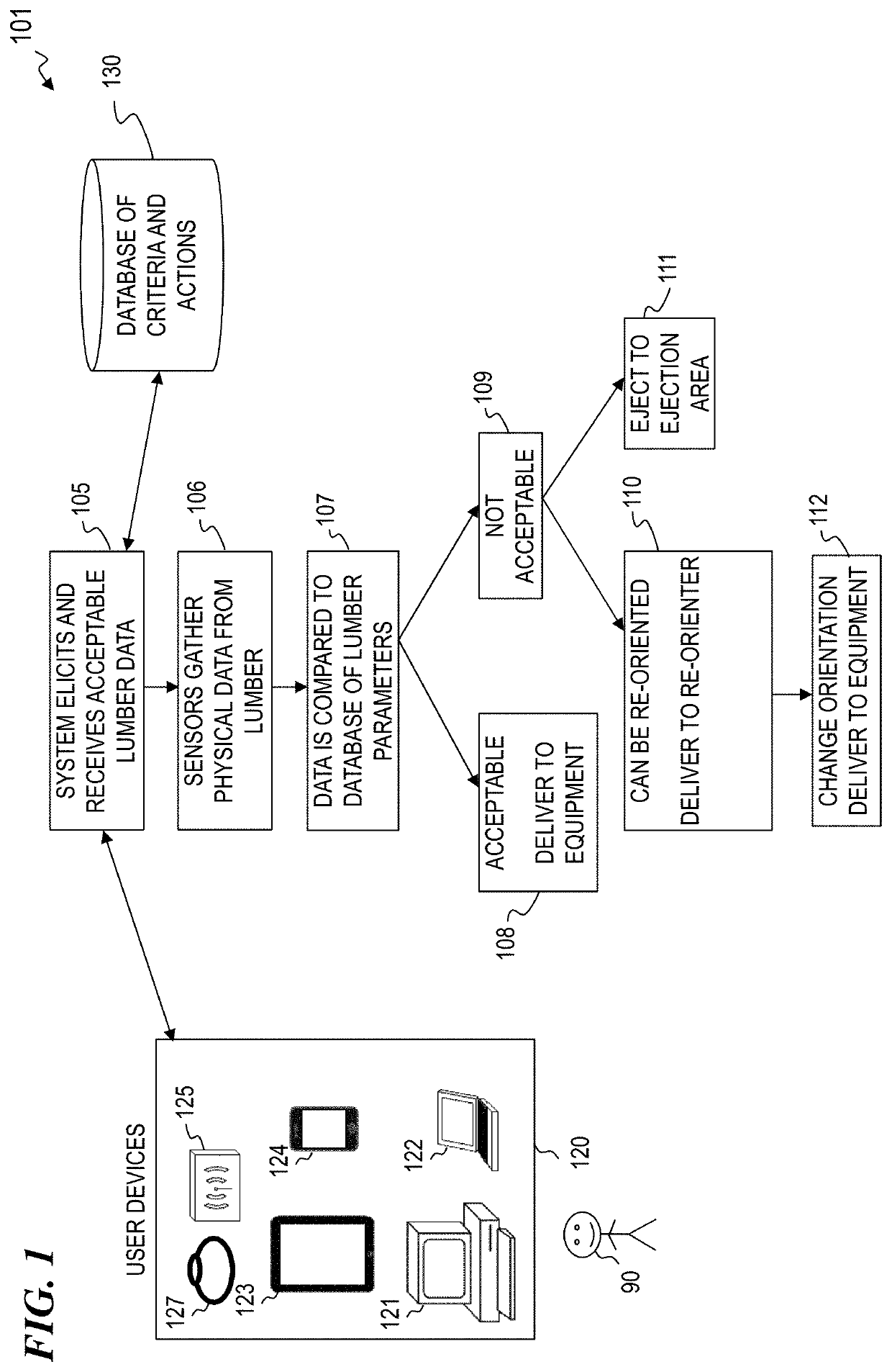
[0018]In some embodiments, the present invention provides a method and associated system that includes a computer processor, wherein the computer processor includes: a plurality of input data devices, a plurality of output data devices, and a plurality of sensors, and wherein the system further includes a mechanical assembly integrated with the computer processor to analyze the geometry of a piece of wood or lumber and, if necessary, reposition the piece and convey the piece to a saw or to a reject station, based on software code executing in the computer processor. Some embodiments organize each incoming stack of lumber in one of a plurality of vertically spaced apart bunks, one on top of another, and provide a gantry that picks a selected board from the stack of lumber on a selected bunk, and moves to board in a direction generally parallel to the long axis of the board from the bunk to one of a plurality of processing stations, wherein the plurality of processing stations includes a flipping station and / or a sawing station. Organizing the lumber bunks in vertical assemblies greatly reduces the footprint of the overall system, thus making more efficient use of valuable factory space and reducing costs. Using the present invention, one can buy lower-grade lumber and sort the boards to obtain suitable and usable pieces for a given end product, thus reducing cost and improving quality of the end product.

Problems solved by technology

One problem with today's conventional technology is that, when manually loading wood into the infeed systems, the human operator needs to determine how to orient the wood, which increases the cost of labor when manufacturing structures using wood boards (lumber).
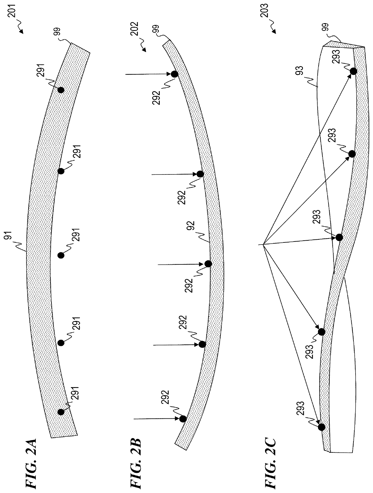
Conventional automated or partially automated systems are unable to determine and / or distinguish the crown of the lumber.

Method used


Image

  • Automated system and method for lumber analysis
  • Automated system and method for lumber analysis
  • Automated system and method for lumber analysis

Examples


Embodiment Construction

[0038]Although the following detailed description contains many specifics for the purpose of illustration, a person of ordinary skill in the art will appreciate that many variations and alterations to the following details are within the scope of the invention. Specific examples are used to illustrate particular embodiments; however, the invention described in the claims is not intended to be limited to only these examples, but rather includes the full scope of the attached claims. Accordingly, the following preferred embodiments of the invention are set forth without any loss of generality to, and without imposing limitations upon the claimed invention. Further, in the following detailed description of the preferred embodiments, reference is made to the accompanying drawings that form a part hereof, and in which are shown by way of illustration specific embodiments in which the invention may be practiced. It is understood that other embodiments may be utilized and structural change...


PUM


Abstract

A system that includes a computer processor having a plurality of input data devices, a plurality of output data devices, and a plurality of sensors; and a mechanical assembly integrated with the computer processor to reposition a piece of wood lumber based on software code executing in the computer processor. In some embodiments, the system performs a method that includes eliciting and receiving into the computer processor data parameters from a first human user; obtaining incoming data points about the lumber from the plurality of sensors; processing and storing the data parameters; comparing the incoming data points to the data parameters to obtain comparison results; and, based on the comparison results, (1) rejecting the lumber to a preprogrammed position, (2) feeding the lumber into a saw assembly as positioned, or (3) repositioning the lumber to a more optimal position prior to feeding the lumber to the saw assembly.

Description

CROSS-REFERENCE TO RELATED APPLICATION[0001]This application claims priority benefit, under 35 U.S.C. § 119(e), of U.S. Provisional Patent Application No. 62 / 388,048, filed Jan. 14, 2016 by Steven Weinschenk, titled “AUTOMATED SYSTEM AND METHOD TO ENHANCE SAFETY AND STRENGTH OF WOOD TRUSS STRUCTURES,” which is incorporated herein by reference in its entirety.[0002]This invention is related to:[0003]U.S. Provisional Patent Application 62 / 144,859 filed Apr. 8, 2015 by Steven Weinschenk, titled “DIGITAL PROJECTION SYSTEM AND METHOD FOR WORKPIECE ASSEMBLY”;[0004]U.S. patent application Ser. No. 15 / 093,732 filed Apr. 7, 2016 by Steven R. Weinschenk et al., titled “DIGITAL PROJECTION SYSTEM AND METHOD FOR WORKPIECE ASSEMBLY” (which issued as U.S. Pat. No. 10,210,607 on Feb. 19, 2019); which are both incorporated herein by reference in their entirety.FIELD OF THE INVENTION[0005]The present invention relates to devices and methods to workpiece assembly, and in particular to automated system...

Claims


Application Information

Patent Timeline
Patent Type & Authority Patents(United States)
IPC IPC(8): G06K9/00B27B25/00B27B31/04B27B1/00H04N5/247G06T7/00
CPCG06T7/001H04N5/247B27B31/04B27B25/00B27B1/007G06T7/0006G06T2207/30161B27B31/06B07C5/342B07C5/14G06F30/13H04N23/90
Inventor WEINSCHENK, STEVEN R.
Owner WEIN HLDG LLC
Learn More