Lower vehicle-body structure of automotive vehicle

a vehicle body and lower technology, applied in the direction of superstructure connections, superstructure subunits, vehicle arrangements, etc., can solve the problems of deteriorating ride comfort of passengers, vibration may be transmitted to passengers improperly, and the upper face portion may be easily deformed, so as to improve the rigidity of the surface

Active Publication Date: 2020-03-10
MAZDA MOTOR CORP
View PDF6 Cites 2 Cited by
  • Summary
  • Abstract
  • Description
  • Claims
  • Application Information

AI Technical Summary

Benefits of technology

[0009]In view of the above-described problems, an object of the present invention is to provide a lower vehicle-body structure of an automotive vehicle which can improve the surface rigidity of the upper face portion of the seat-attaching bracket, without deteriorating its serving as the load transmission path where the side-collision load from the vehicle side is transmitted.

Problems solved by technology

Further, since a weight of the passenger tends to act on the rear portion of the seat in a state where the passenger is seated, there is a problem that if the surface rigidity of the upper face portion is low, the upper face portion may be easily deformed due to vertically-directional vibration of a vehicle body which is generated during vehicle traveling in a case where the seat-attaching bracket (connecting member 35) supports the rear portion of the seat as disclosed in the above-described patent document.
In this case where the upper face portion is easily deformed due to the vertically-directional vibration of the vehicle body, when the automotive vehicle rides over a slope, for example, the upper face portion of the seat-attaching bracket (connecting member 35) starts its deformation in an early stage, so that there is a concern that an urethane cushion forming the seat may not sufficiently damp the vertically-directional vibration of the vehicle body, so that the vibration may be transmitted to the passenger improperly.
Thereby, a head portion of the passenger is forced to swing, so that there is a concern that the ride comfort of the passenger may be deteriorated.

Method used


Image

  • Lower vehicle-body structure of automotive vehicle
  • Lower vehicle-body structure of automotive vehicle
  • Lower vehicle-body structure of automotive vehicle

Examples


embodiment 1

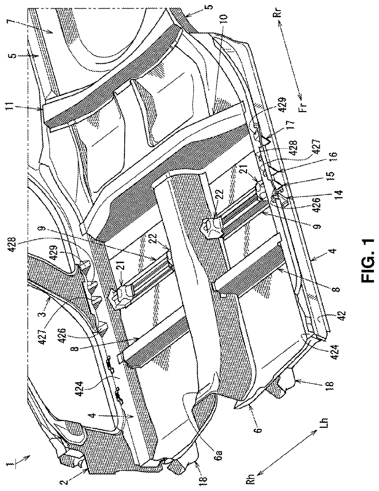
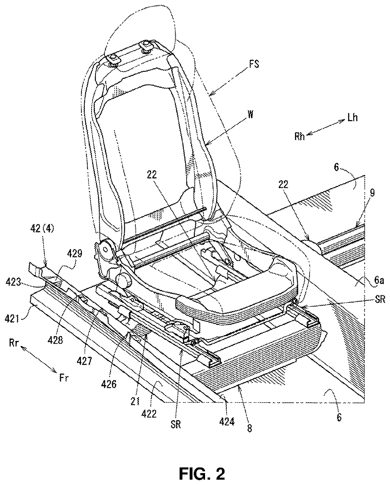
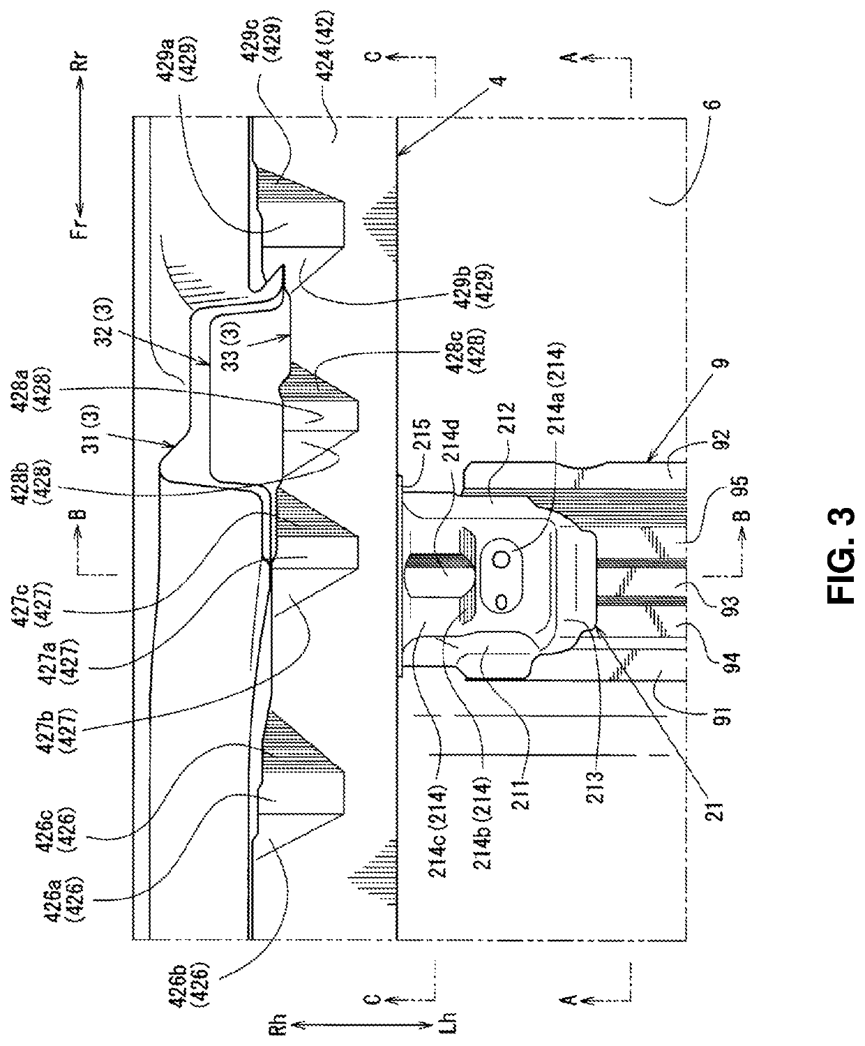
[0045]A lower-vehicle body structure of an automotive vehicle 1 according to a first embodiment will be described specifically referring to FIGS. 1 through 7. Herein, FIG. 1 is a perspective view showing an external appearance of a lower vehicle body of the automotive vehicle 1, FIG. 2 is a perspective view showing an external appearance of the lower vehicle body of the automotive vehicle 1 in a state where a front seat FS is installed, FIG. 3 is a plan view showing an external appearance a part of the lower vehicle body near a center pillar 3, FIG. 4 is a side view showing a side face of the part of the lower vehicle body taken along line A-A of FIG. 3, FIG. 5 is a sectional view taken along line B-B of FIG. 3, FIG. 6 is a perspective view showing an external appearance of a part of the lower vehicle body near a lower portion of the center pillar 3, and FIG. 7 is a sectional view taken along line C-C of FIG. 3.

[0046]In order to clarify illustrations, an external appearance of the f...

embodiment 2

[0138]Next, a second embodiment of the lower vehicle-body structure of the automotive vehicle 1 in which the shape of the side sill inner panel 42 of the side sill 4 and the shape of the first seat-attaching bracket 21 are respectively different from those of the above-described lower vehicle-body structure of the automotive vehicle 1 of the first embodiment will be described specifically referring to FIGS. 8 through 11.

[0139]Herein, FIG. 8 is a perspective view showing an external appearance of the lower vehicle body of the second embodiment, FIG. 9 is a plan view showing a part of the lower vehicle body of the second embodiment near the center pillar 3, FIG. 10 is a side view showing a side face of the part of the lower vehicle body taken along line D-D of FIG. 9, and FIG. 11 is a sectional view taken along line E-E of FIG. 9. The same structures as the first embodiment are denoted by the same reference characters, specific descriptions of which are omitted.

[0140]First, similarly ...


PUM


Abstract

In a lower vehicle-body structure of an automotive vehicle comprising a pair of right-and-left side sills, a floor panel, and a first seat-attaching bracket supporting a front seat, an upper wall portion of the first seat-attaching bracket comprises an attachment portion to which the front seat is attached, a slant portion (connection portion) which extends downward from an outward-side edge side of the attachment portion, and a stepped-down portion which extends from the slant portion toward the side sill, and a bead which protrudes upward and extends from the slant portion toward the side sill in the vehicle width direction is provided at the stepped-down portion.

Description

BACKGROUND OF THE INVENTION[0001]The present invention relates to a lower vehicle-body structure of an automotive vehicle which comprises a seat-attaching bracket supporting a seat where a passenger is seated.[0002]In general, the seat where the passenger is seated is fixed to a portion of a vehicle body which has relatively-high rigidity in a cabin of the automotive vehicle in order to secure the ride comfort (ride quality) of the passenger. For example, in a structure disclosed in Japanese Patent Laid-Open Publication No. 2010-228482, a front portion of the seat where the passenger is seated is supported at a cross member 20 (No. 2 cross member) which interconnects right-and-left side sills 6 via a tunnel portion 2 of a floor panel 1 which forms a bottom face of the cabin.[0003]Meanwhile, a rear portion of the seat is supported at a seat-attaching bracket (connecting member 35) which is joined both to a cross member 30 (No. 2.5 cross member) interconnecting the right-and-left side...

Claims


Application Information

Patent Timeline
Patent Type & Authority Patents(United States)
IPC IPC(8): B62D25/20B62D27/02B62D21/15B62D21/03B62D25/04B60N2/015B62D25/02
CPCB62D27/023B60N2/015B62D25/025B62D21/157B62D25/04B62D25/2036B62D21/03B62D25/20B60N2/0715
Inventor KAGEYAMA, KAZUHIROGOTO, HIDETAKASAKOMOTO, SHOGO
Owner MAZDA MOTOR CORP
Why Eureka
Try Eureka