Variable geometry and steady volume inflatable tube, robotic arm and robot
a technology of inflatable tubes and constant volume, applied in the field of joints of polyarticulated robotic arms, can solve the problems of limiting the slenderness which can be achieved in practice, seams turned out to be rather complex to make in an industrial context, and achieve the effect of satisfying torsional rigidity
- Summary
- Abstract
- Description
- Claims
- Application Information
AI Technical Summary
Benefits of technology
Problems solved by technology
Method used
Image
Examples
first embodiment
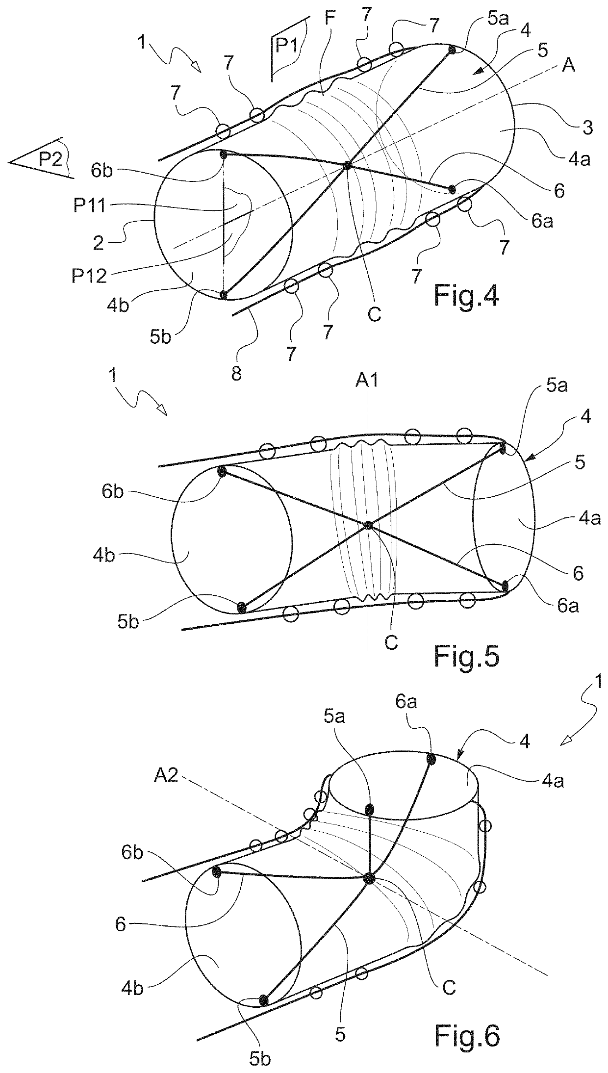
[0062]Firstly, with reference to FIG. 4, it can be seen that a part of a robotic arm according to the present invention is shown schematically therein.
[0063]Such a robotic arm comprises an inflatable tube 1 which is configured to be inflated by an air-type fluid or a liquid-type fluid, even an heterogeneous mixture comprising solids, and has a fluid inlet end 2 and a fluid outlet end 3. The fluid inlet and fluid outlet ends 2, 3 can advantageously be combined.
[0064]The fluid inlet and fluid outlet ends 2, 3 are schematically shown in FIG. 4. Thus, the fluid inlet end 2 can be sealingly linked to a compressor or to a fan, in order to cause a fluid to flow to the fluid outlet end 3 and thus to inflate the inflatable tube 1. The fluid inlet end 2 can also be closed, a gas cartridge causing the fluid to flow to the fluid outlet end 3 in order to inflate the inflatable tube 1.
[0065]The fluid outlet end 3 is in turn closed, and may, when the inflatable tube 1 is used on a robotic arm or a...
second embodiment
[0089]Now, with reference to FIGS. 9 to 13, it can be seen that an inflatable tube 10 according to the present invention is shown therein, which embodiment is based on the same principle of concentrating on the central axis A, by inextensible linking means, longitudinal tensile stresses exerted on the envelope when the inflatable tube 10 is pressurized.
[0090]The inflatable tube 10 here again comprises fluid inlet 12 and fluid outlet 13 ends on the same principle as the ends 2 and 3 of the first embodiment, and an envelope 4.
[0091]The inflatable tube 10 is noteworthy in that the inextensible linking means extend both in the first longitudinal mid-plane P1 of the envelope 14, but also in the second longitudinal mid-plane P2, thus dividing the inside of the envelope 14 into four compartments Cp1, Cp2, Cp3 and Cp4.
[0092]Such a configuration allows to distribute the stresses even better in the envelope 14 when the inflatable tube 10 bends.
[0093]It is illustrated in a schematic way in FIG...
PUM
 Abstract
Description
Claims
Application Information
 - R&D
- Intellectual Property
- Life Sciences
- Materials
- Tech Scout
- Unparalleled Data Quality
- Higher Quality Content
- 60% Fewer Hallucinations
Browse by: Latest US Patents, China's latest patents, Technical Efficacy Thesaurus, Application Domain, Technology Topic, Popular Technical Reports.
© 2025 PatSnap. All rights reserved.Legal|Privacy policy|Modern Slavery Act Transparency Statement|Sitemap|About US| Contact US: help@patsnap.com


