A Kinematic Mechanism with Flexible and Variable Rigidity

A technology of motion mechanism and drive mechanism, which is applied in the field of power manipulators, can solve the problems of small application range, insufficient flexibility of motion mechanism, and inability to realize rigidity flexible free transformation, etc., and achieve the effect of free switching and convenient use

Active Publication Date: 2020-01-10
GUOCHUANG INNOVATION CENTER OF MOBILE ENERGY (JIANGSU) CO.,LTD.
View PDF15 Cites 0 Cited by
  • Summary
  • Abstract
  • Description
  • Claims
  • Application Information

AI Technical Summary

Problems solved by technology

[0006] The present invention aims to solve the problem that the existing kinematic mechanisms are all fixed in kinematic performance, and cannot realize rigidity, flexibility and free transformation, so that the kinematic mechanism is not flexible enough, and the application range is small. Therefore, a high-precision automatic charging vehicle guidance and positioning system is provided.

Method used


Image

  • A Kinematic Mechanism with Flexible and Variable Rigidity
  • A Kinematic Mechanism with Flexible and Variable Rigidity
  • A Kinematic Mechanism with Flexible and Variable Rigidity

Examples


Embodiment 1

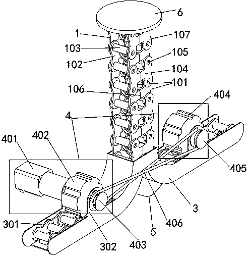
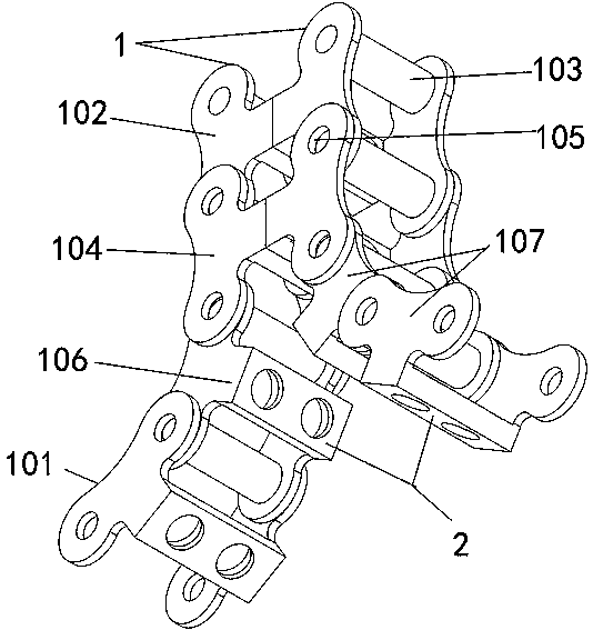
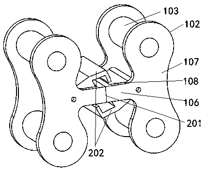
[0032] A kinematic mechanism with flexible and variable rigidity, comprising a kinematic chain 1 and a driving mechanism 4, the kinematic chain 1 moves through the driving mechanism 4, the kinematic chain 1 includes two symmetrically installed kinematic single chains 101, the kinematic single chain The chain 101 includes a number of inner sections 102 and a number of outer sections 104, the inner sections 102 and the outer sections 104 are composed of two joint pieces 107, and two hinge base columns are arranged between the two joint pieces 107 of the inner section 102 103, there are two hinge base holes 105 penetrating between the two joint pieces 107 of the outer section 104, the hinge base column 103 at the lower end of the inner section 102 and the hinge base hole 105 at the upper end of the outer section 104 are movably installed, the The hinged base column 103 at the upper end of the inner section 102 and the hinged base hole 105 at the lower end of the other outer sectio...

Embodiment 2

[0042] A kinematic mechanism with flexible and variable rigidity, comprising a kinematic chain 1 and a driving mechanism 4, the kinematic chain 1 moves through the driving mechanism 4, the kinematic chain 1 includes two symmetrically installed kinematic single chains 101, the kinematic single chain The chain 101 includes a number of inner sections 102 and a number of outer sections 104, the inner sections 102 and the outer sections 104 are composed of two joint pieces 107, and two hinge base columns are arranged between the two joint pieces 107 of the inner section 102 103, there are two hinge base holes 105 penetrating between the two joint pieces 107 of the outer section 104, the hinge base column 103 at the lower end of the inner section 102 and the hinge base hole 105 at the upper end of the outer section 104 are movably installed, the The hinged base column 103 at the upper end of the inner section 102 and the hinged base hole 105 at the lower end of the other outer sectio...

Embodiment 3

[0052] A kinematic mechanism with flexible and variable rigidity, comprising a kinematic chain 1 and a driving mechanism 4, the kinematic chain 1 moves through the driving mechanism 4, the kinematic chain 1 includes two symmetrically installed kinematic single chains 101, the kinematic single chain The chain 101 includes a number of inner sections 102 and a number of outer sections 104, the inner sections 102 and the outer sections 104 are composed of two joint pieces 107, and two hinge base columns are arranged between the two joint pieces 107 of the inner section 102 103, there are two hinge base holes 105 penetrating between the two joint pieces 107 of the outer section 104, the hinge base column 103 at the lower end of the inner section 102 and the hinge base hole 105 at the upper end of the outer section 104 are movably installed, the The hinged base column 103 at the upper end of the inner section 102 and the hinged base hole 105 at the lower end of the other outer sectio...


PUM


Abstract

The invention provides a motion mechanism with variable rigidity and flexibility. The motion mechanism comprises a motion chain and a drive mechanism, the motion chain comprises two symmetrically installed motion single chains, each motion single chain comprises a plurality of inner sections and a plurality of outer sections, each of the inner sections and the outer sections is formed by two contact sheets, two hinge foundation pillars are arranged between the two contact sheets of each inner section, two hinge base holes penetrate the position between the two contact sheets of each outer section, the hinge foundation pillar at the lower end of the inner section is movably installed with the hinge base hole at the upper end of the outer section, the hinge foundation pillar at the upper endof the inner section is movably installed with the hinge base hole at the lower end of the other section, the inner sections and the outer sections are installed in order from top to bottom at intervals, connection bulges are arranged at the middle positions of the sides of the contact sheets of the inner sections and the outer sections, the end faces of the connection bulges are provided with locking mechanisms, and a charging execution device is installed above the motion chains. The motion mechanism with variable rigidity and flexibility solves the problems that a current motion mechanismhas a fixed motion performance and cannot achieve free conversion of the rigidity and the flexibility so that the motion mechanism is not flexible enough and is small in application range.

Description

technical field [0001] The invention belongs to the technical field of power mechanical arms, and is mainly used for a charging port lifting structure of a car charging pile, and in particular relates to a motion mechanism with flexible and variable rigidity. Background technique [0002] At present, there are many kinds of common vertical / horizontal telescopic lifting mechanism schemes, such as hydraulic cylinders, air cylinders, electric cylinders, X-arms, Z-arms, and movable pulley blocks. They have their own working conditions, their own advantages and disadvantages. [0003] There is a special working condition that requires the lifting mechanism to be compressed into a plane when it is retracted, and the smaller the volume, the better; when rising, the raised height should be at least 6 times the vertical height when retracted; there is a certain rigidity when rising, But it has a certain degree of flexibility; when it is raised to the right position, it can be flexibl...

Claims


Application Information

Patent Timeline
Patent Type & Authority Patents(China)
IPC IPC(8): B60L53/35B60L53/16
CPCB60L53/16B60L53/35Y02T10/70Y02T10/7072Y02T90/12Y02T90/14
Inventor 王钰鸣曹伟马秋阁冯宇郑隽一张育铭李德胜
Owner GUOCHUANG INNOVATION CENTER OF MOBILE ENERGY (JIANGSU) CO.,LTD.
Why Eureka
Try Eureka