Distress flare

a technology of distress flare and flare, which is applied in the field of distress flare, can solve the problems of short duration of visible light emitted by distress flare, insatiable distress flare known in the prior art, and inability to achieve satisfactory distress flare

Active Publication Date: 2020-03-17
COMMISSARIAT A LENERGIE ATOMIQUE ET AUX ENERGIES ALTERNATIVES
View PDF20 Cites 1 Cited by
  • Summary
  • Abstract
  • Description
  • Claims
  • Application Information

AI Technical Summary

Benefits of technology

[0015]The implementation of the inflatable shell allows the visible light emitted by the illuminating means to be diffused in an essentially isotropic manner.
[0022]The light emitting diodes allow an optimized management of the energy they consume, and thus allow the emission duration of the visible light to be extended compared to known distress flares of the prior art.
[0023]Moreover, the light emitting diodes consume little energy, and thus do not require the carriage of a large quantity of energy.
[0026]The implementation of the luminophores also boosts the isotropic diffusion of the light.
[0035]According to one embodiment, the control module further controls the activation of the deploying means; advantageously, the control module is suitable for imposing the activation thereof when the distress flare has reached a maximum altitude.

Problems solved by technology

However, this distress flare known in the prior art is not satisfactory.
More specifically, the duration of the visible light emitted by the distress flare, which is dependent on the pyrotechnic charge, is relatively short and only allows for a short period of time for it to be spotted by an emergency rescue service for example.
The carriage of a larger pyrotechnic charge in order to increase the emission duration generates an undesired risk, in particular in an emergency situation.

Method used


Image

  • Distress flare

Examples


Embodiment Construction

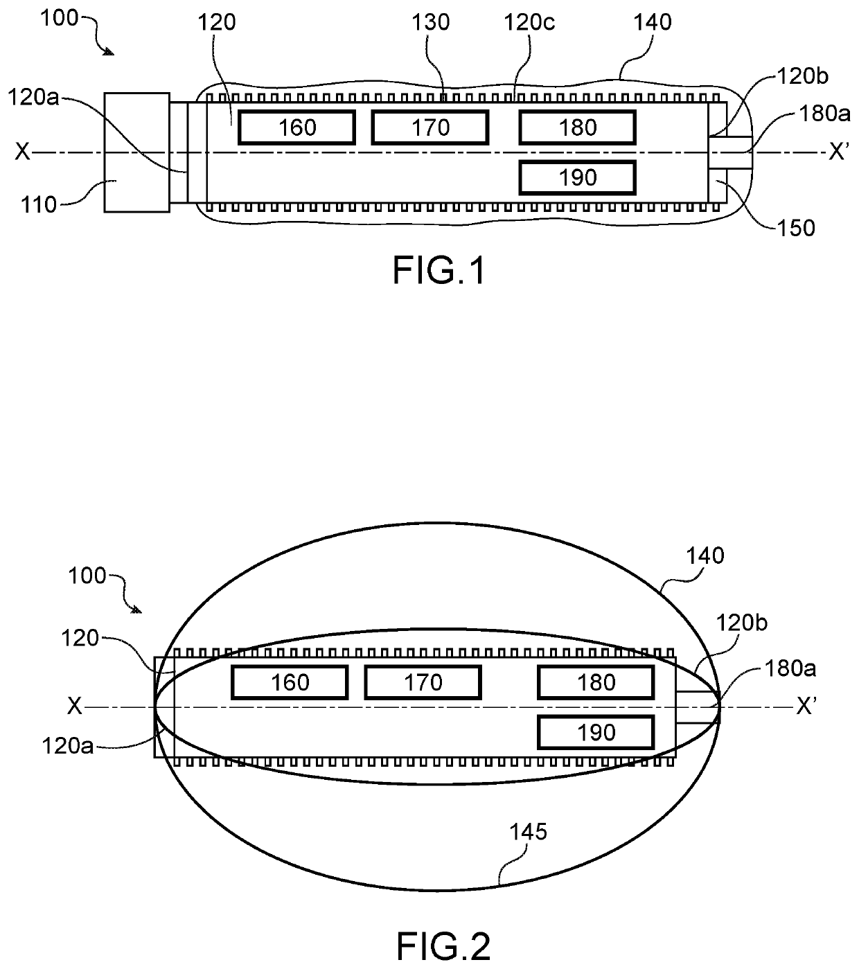
[0010]This invention relates to a distress flare provided with a cartridge and activation means intended to propel said cartridge into the sky.

[0011]According to one embodiment of this invention, the activation means comprise a case provided with a pyrotechnic charge, referred to as an expelling charge, intended to expel the cartridge.

[0012]The cartridge further comprises illuminating means capable of emitting visible light, in particular light emitting diodes, arranged on a side surface that connects the two ends of the cartridge.

[0013]The illuminating means are, as understood in this invention, powered by a battery.

[0014]In a particularly advantageous manner, the distress flare comprises an inflatable shell, covering the side surface, suitable for being deployed under the effect of deploying means and of diffusing the visible light.

[0015]The implementation of the inflatable shell allows the visible light emitted by the illuminating means to be diffused in an essentially isotropic ...


PUM


Abstract

A distress flare including a cartridge including two ends connected by a side surface; activation device intended to expel the cartridge into the sky; an inflatable shell, covering the side surface, suitable for being deployed under the effect of deploying device and of diffusing the visible light; illuminating device powered by a battery and capable of emitting visible light, the illuminating device being arranged on the side surface.

Description

TECHNICAL FIELD[0001]This invention relates to a distress flare. In particular, this invention relates to a distress flare provided with illuminating means, in particular light emitting diodes, powered by a battery. According to a particularly advantageous feature, the distress flare is provided with an inflatable shell which, when deployed, diffuses the visible light emitted by the illuminating means in an isotropic manner.PRIOR ART[0002]A distress flare known in the prior art comprises a pyrotechnic charge which, when being consumed, emits very intense visible light intended to signal an emergency and / or dangerous situation.[0003]The distress flare is generally propelled to an altitude of several hundred meters such that the visible light can be spotted over a long distance, for example several kilometers.[0004]However, this distress flare known in the prior art is not satisfactory.[0005]More specifically, the duration of the visible light emitted by the distress flare, which is d...

Claims


Application Information

Patent Timeline
Patent Type & Authority Patents(United States)
IPC IPC(8): F42B12/42F42B4/28F42B12/36G08B5/00F42B4/26
CPCG08B5/002F42B12/365F42B4/26F42B12/42F42B4/28
Inventor BERSENEFF, BORISCHATROUX, DANIEL
Owner COMMISSARIAT A LENERGIE ATOMIQUE ET AUX ENERGIES ALTERNATIVES
Why Eureka
Try Eureka