Powertrain assembly and vehicle comprising the same

a technology of powertrain and assembly, which is applied in the direction of vehicle position/course/altitude control, process and machine control, instruments, etc., can solve the problems of engine piston sliding force, unknown load, drag loss in the piston, rod, valve-train of internal combustion engine,

Inactive Publication Date: 2015-10-08
AB SKF
View PDF8 Cites 0 Cited by
  • Summary
  • Abstract
  • Description
  • Claims
  • Application Information

AI Technical Summary

Benefits of technology

The patent describes a freewheel that can improve energy management in electric vehicles by storing and retrieving rotational energy without drag losses. It also eliminates the need for expensive super-capacitors and increases the total energy storage capacity. The freewheel can be used in an assisted acceleration mode to provide additional traction power without overloading the main battery and can be driven motor mode to accelerate the rotor using electrical energy from the main storage system. These features can lead to a more compact design, cost-saving, and better performance of electric vehicles.

Problems solved by technology

This solution leads to various problems.
Firstly, non-perfect coaxiality between the splined shafts leads to wear and induces unknown loads towards the rolling bearings and the crankshaft sliding bushings of the internal combustion engine.
Further, the fixed connection may lead to drag losses in the pistons, rods, valve-trains of the internal combustion engine etc. when the vehicle speed is decreasing in case the range-extender system (it means one internal combustion engine and its associated electric generator) would have additional function to convert vehicle mechanical energy into electrical energy, in order to recover braking energy.
However, sliding forces from engine pistons into cylinder, valves into their guides and valves seals, as well as friction torques from rotary crankshaft, camshaft(s), balancing shaft(s) and from crankshaft driven alternator, air conditioning compressor, water-pump, hydraulic steering pump, all unavoidable, if internal combustion engine is not dis-clutched or free-wheeled from vehicle wheels, during each vehicle decelerations.
In particular, the high energy amounts generated during short-time regenerative vehicle braking operations cannot be efficiently charged in modern batteries without damaging them.
Both solutions require additional energy storing systems which are expensive, susceptible to internal damages and consuming space and weight on-board vehicles.
Mechanical and electrical KERS may generate people injuries if given failures at high-speed, depending from their very high speed rotor geometry and material as well as from its container wall thickness design.

Method used


Image

  • Powertrain assembly and vehicle comprising the same
  • Powertrain assembly and vehicle comprising the same
  • Powertrain assembly and vehicle comprising the same

Examples


first embodiment

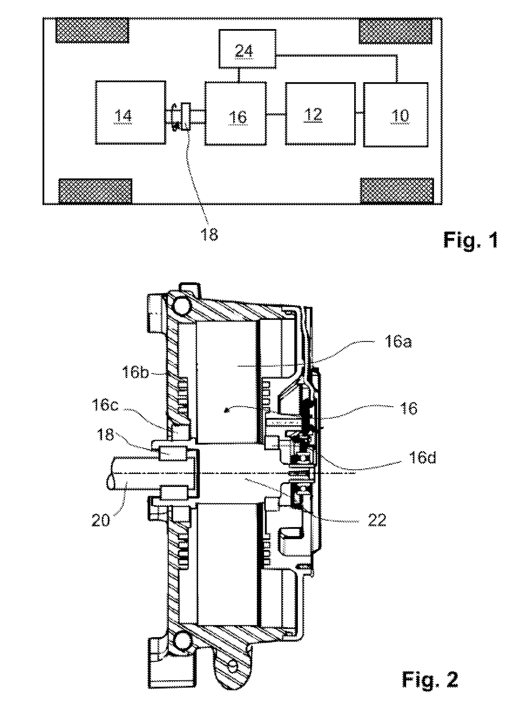
[0031]FIG. 1 is a schematic view of a vehicle comprising a powertrain assembly according to the invention.

[0032]The vehicle is a vehicle having electric traction motor 10 powered by accumulators forming a main electrical energy storage system 12 for storing electrical energy for driving the electrical traction motor 10 and with a range extender assembly.

[0033]The range extender assembly comprises an internal combustion engine 14 and a reversible electric machine 16, wherein the internal combustion engine 14 and the reversible electric machine 16 are connected by a torque transmission path created by a power train assembly comprising a free-wheel 18 mounted in the torque transmission path.

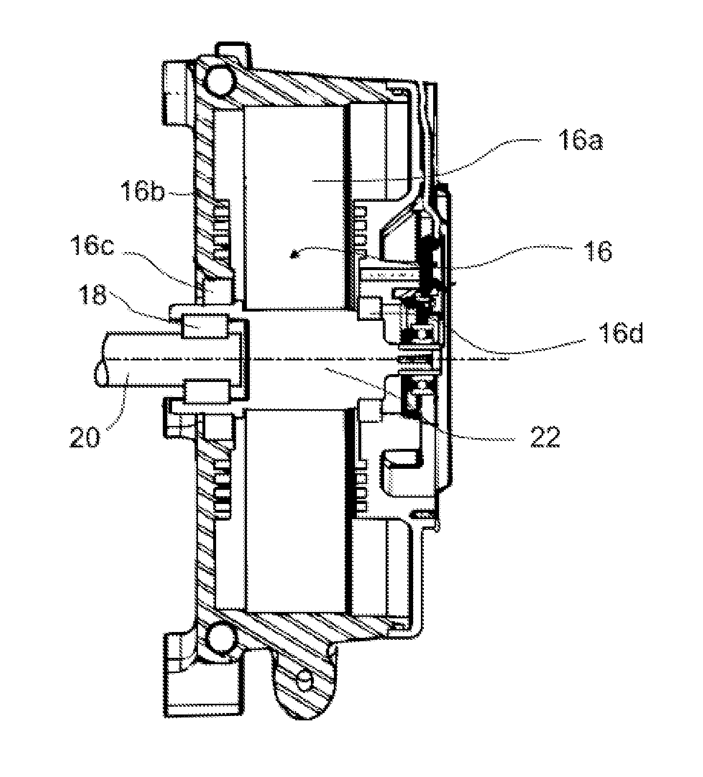
[0034]FIG. 2 is a sectional view of a portion of the torque transmission path of the powertrain assembly according to the first embodiment of invention including the free-wheel 18.

[0035]The reversible electric machine 16 comprises a rotor 16a in a housing 16b provided with stator windings. The rotor...

second embodiment

[0047]FIG. 4 is a schematic view of a vehicle according to the invention the invention including locking feature 26 for the freewheel 18. The locking of the free-wheel 18 enables torque transmissions in both rotation directions.

[0048]In this embodiment, the control unit 24 may be equipped with software enabling driving the reversible electric machine 16 in order to start the internal combustion engine 14 of the range extender such that any additional starting system connected to the internal combustion engine 14 with a belt, can be dispensed with.

[0049]This construction with lockable-on-demand free-wheel installed between internal combustion engine 14 and reversible electric machine 16 saves mass and cost of any additional system to start internal combustion engine 14. For example below additional systems will be eliminated: one starter gear-motor with moveable starter-pinion and its one way clutch, to be electro-mechanically geared then un-geared on demand onto internal combustion ...

third embodiment

[0051]FIG. 5 is a schematic view of a vehicle according the invention including an engageable and disengageable clutch 28 connected parallel to the freewheel 18. In the disengaged configuration, the rotor 16a of the reversible electric machine 16 can be used as energy storage system as described above. In the engaged configuration, the reversible electric machine 16 can be used as starting electric machine to start rotary motion and then self ignition of the internal combustion engine 14 of the range extender.


PUM


Abstract

A powertrain assembly for creating a torque transmission path between an internal combustion engine and a rotor of a reversible electric machine and to a vehicle comprising such a powertrain assembly. The powertrain assembly includes a freewheel in the torque transmission path.

Description

CROSS REFERENCE TO RELATED APPLICATIONS[0001]This is a Non-Provisional Patent Application, filed under the Paris Convention, claims the benefit of European Patent (EP) Application Number 14305507.7 filed on 7 Apr. 2014 (07.04.2014), which is incorporated herein by reference in its entirety.FIELD OF THE INVENTION[0002]The invention relates to powertrain assemblies creating a torque transmission path between an internal combustion engine and a rotor of a reversible electric machine.PRIOR ART[0003]Power train assemblies of this type are frequently used in the field of range-extenders for vehicles comprising electrical traction motors. The internal combustion engine of the range extender assembly can be used to drive the reversible electric machine acting as a generator in order to produce additional electric energy for driving the traction motor in the event that the initially stored electric energy stored in the battery of the vehicle is used up.[0004]In known range-extender assemblie...

Claims


Application Information

Patent Timeline
Patent Type & Authority Applications(United States)
IPC IPC(8): B60K6/383F16D47/04B60W20/00F16D41/07B60L50/15
CPCB60K6/383F16D41/07Y10S903/903B60W20/1062F16D47/04B60K6/105B60K6/46B60W10/02B60W10/06B60W10/08B60W20/14B60K6/10B60W30/18127F16D41/04Y02T10/62
Inventor DESCOMBES, MICHEL
Owner AB SKF
Why Eureka
Try Eureka