Self-propelled floor treatment device

a floor treatment and self-propelled technology, applied in the direction of carpet cleaners, electric equipment installation, cleaning action control, etc., can solve the problems of floor treatment devices that drift on the surface, floor treatment devices that drift, etc., and achieve the effect of improving cleaning performan

Active Publication Date: 2020-03-31
VORWERK & CO INTERHOLDING GMBH
View PDF3 Cites 0 Cited by
  • Summary
  • Abstract
  • Description
  • Claims
  • Application Information

AI Technical Summary

Benefits of technology

[0007]Proceeding from the aforementioned prior art, it is thus the object of the invention to provide a floor treatment device with a detection device that makes it possible to reliably determine the floor type with a low outlay.
[0015]It can further be provided that the detection device have an optical reflection measuring device with a light source and a light receiver, wherein a light emission direction of the light source is essentially directed toward the ground plane spanned by the wheels. Apart from the frictional resistance element, then, the detection device can also have an optical reflection measuring device for detecting the floor type. For example, the reflection measuring device can be a distance measuring device, which predominantly serves to detect precipices. The light source of the optical reflection measuring device is preferably arranged in the front area of the floor treatment device, so as to protect a floor treatment device traveling forward in the main direction of movement against falling off of stairs or the like, for example. For example, the reflection measuring device can have an infrared light source and an infrared light receiver. The light of the light source is radiated onto the surface to be examined, there reflected, and finally hits the light receiver. Based on the reflectance of the measured surface, the floor type of the surface can be inferred, e.g., since a carpeted floor has a lower reflectance than a hard floor (tiles, wooden floorboards or the like).
[0019]Finally, it can be provided that a power of a fan of the floor treatment device and / or a speed of the floor treatment element be varied as a function of the detected floor type, and / or that information about the detected floor type be stored in a digital area map of the floor treatment device. In particular, an energy management of the floor treatment device can also be optimized as a function of the floor type of the surface to be treated, in particular in relation to a treatment duration for treating a surface, in relation to an improved cleaning performance or the like. In addition, it can also be possible to mark the exact location of detected carpets, tiles, wooden floors and the like in a digital area map, and use this information in future treatment cycles of the floor treatment device.

Problems solved by technology

As a consequence, the frictional resistance exposes the frictional resistance element to a force, which because the frictional resistance is not centrally arranged relative to the wheels causes the floor treatment device to drift on the surface.
What is important is that varyingly large resistance forces act on both sides of the frictional resistance element, thereby causing the floor treatment device to drift.
However, several frictional elements can be arranged on the floor treatment device instead of a single frictional resistance element, which together have an unsymmetrical arrangement and / or formation relative to the reference axis.

Method used


Image

  • Self-propelled floor treatment device
  • Self-propelled floor treatment device
  • Self-propelled floor treatment device

Examples


Embodiment Construction

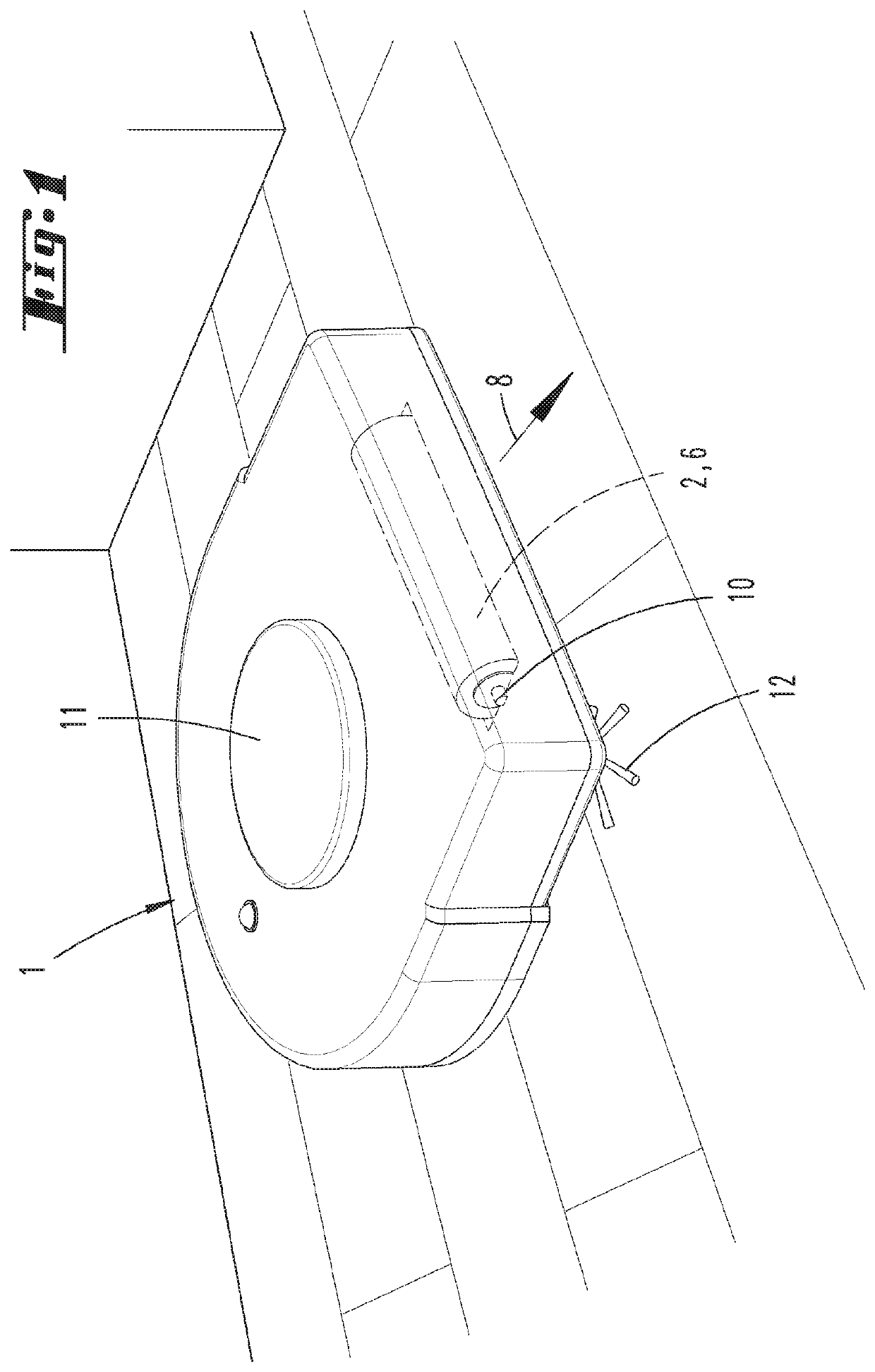
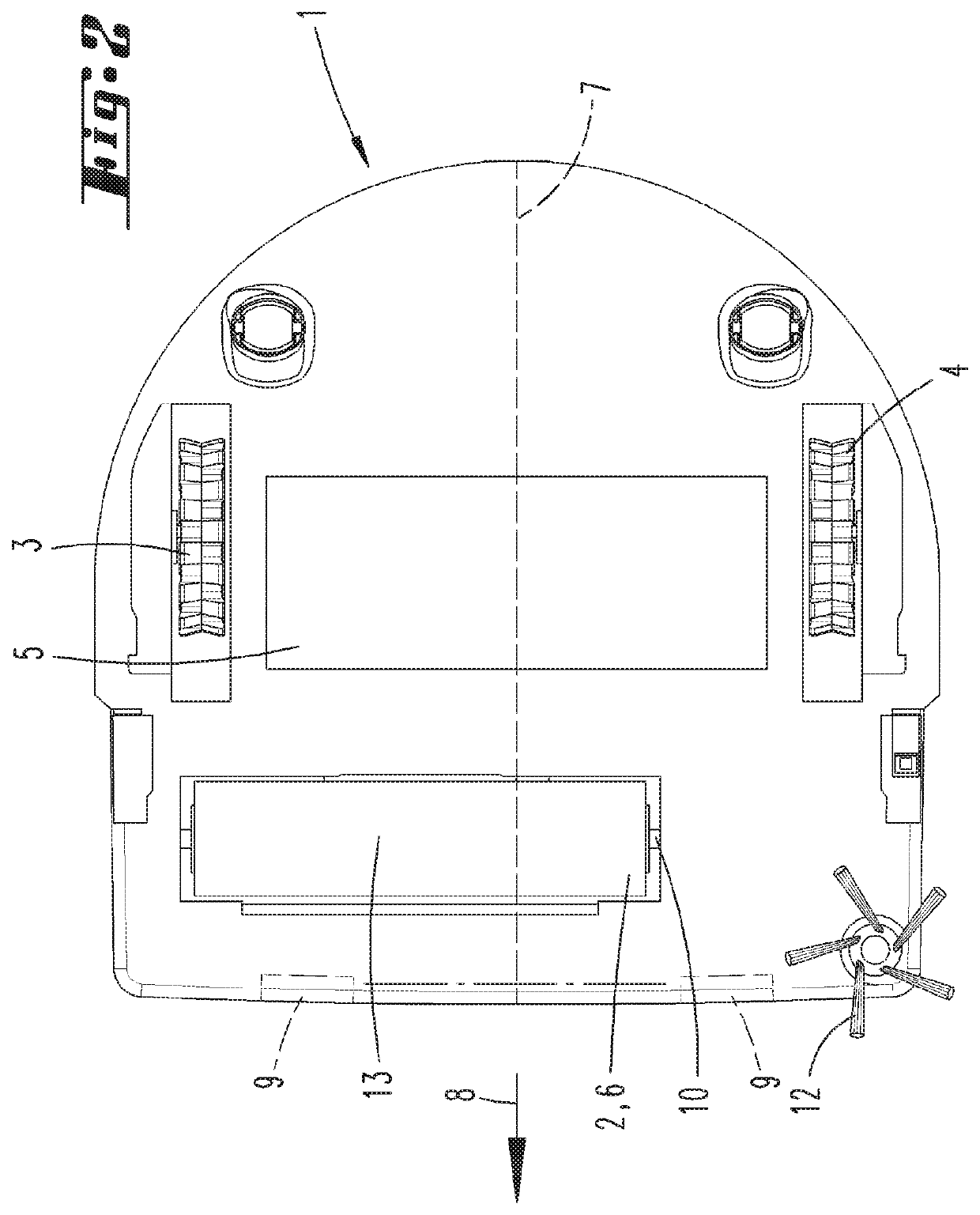
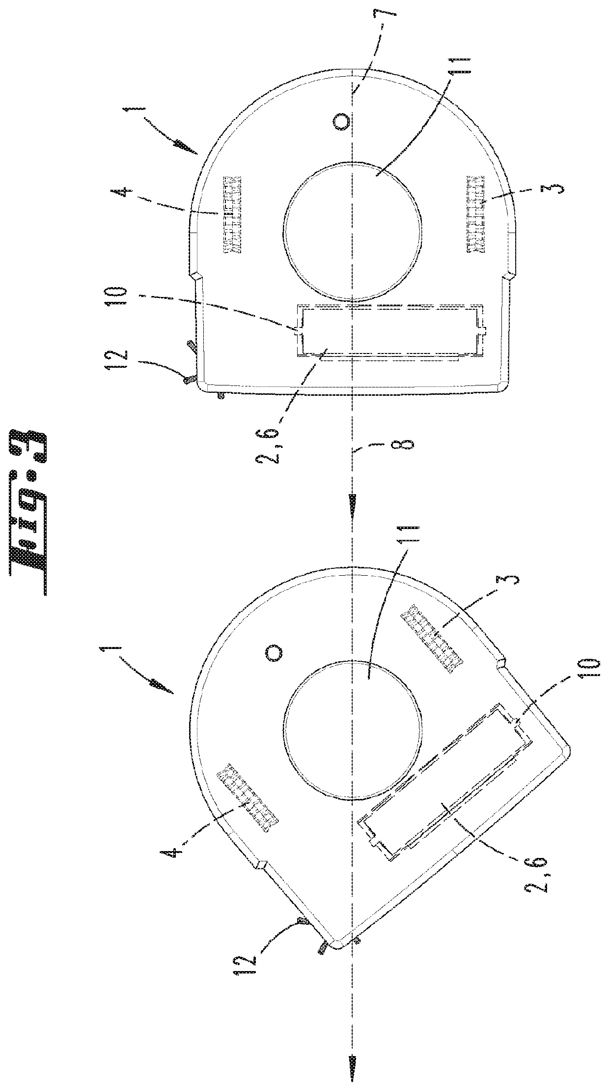
[0024]FIG. 1 shows a floor treatment device 1 according to the invention, which is here designed as a vacuuming robot. The floor treatment device 1 is positioned on a surface, e.g., here a wooden floorboard. The floor treatment device 1 is self-propelled, and has a navigation and self-localization device, which allows an orientation inside of premises. The floor treatment device 1 has two wheels 3, 4 (see FIG. 2) along with a floor treatment element 2, which here is designed like a brush roller. The floor treatment device 1 is supported against the surface to be cleaned by the two wheels 3, 4 on the one hand, and with a contact surface 13 of the floor treatment element 2 on the other, wherein both the wheels 3, 4 for moving the floor treatment device 1 and the floor treatment element 2 for cleaning purposes are motorized. The floor treatment device 1 has a main direction of movement 8, which is prescribed by the rotational plane of the wheels 3, 4. The floor treatment element 2 is a...


PUM


Abstract

The invention relates to a self-propelled floor treatment device (1), in particular to a cleaning robot, with a floor treatment element (2), at least two motorized wheels (3, 4) and a detection device for detecting a floor type of a surface to be treated. In order to easily achieve an optimal detection of the floor type, it is proposed that the detection device have a frictional resistance element (6), which contacts the surface during a movement in such a way that a resultant force outside of a reference axis (7) acts on the floor treatment device (1), wherein the reference axis (7) is oriented parallel to a main direction of movement (8) of the floor treatment device (1) prescribed by the orientation of the wheels (3, 4), and is aligned centrally between the wheels (3, 4) in relation to a direction perpendicular to the reference axis (7). Further proposed is a method for operating a self-propelled floor treatment device (1).

Description

CROSS REFERENCE TO RELATED APPLICATIONS[0001]Applicant claims priority under 35 U.S.C. § 119 of German Application No. 10 2017 101 936.7 filed on Feb. 1, 2017, the disclosure of which is incorporated by reference.[0002]The invention relates to a self-propelled floor treatment device, in particular to a cleaning robot, with a floor treatment element, at least two motorized wheels and a detection device for detecting a floor type of a surface to be treated.[0003]In addition, the invention relates to a method for operating a self-propelled floor treatment device with a floor treatment element, at least two motorized wheels and a detection device for detecting a floor type of a surface to be treated.PRIOR ART[0004]Floor treatment devices of this type are sufficiently known in prior art. For example, these involve vacuuming or wiping robots, which can traverse a surface to be cleaned autonomously and in so doing perform cleaning tasks such as vacuuming, wiping or the like. In order to ad...

Claims


Application Information

Patent Timeline
Patent Type & Authority Patents(United States)
IPC IPC(8): A47L9/28A47L9/04
CPCA47L9/2831A47L9/2847A47L9/2826A47L9/2852A47L9/0411A47L2201/04A47L9/0488A47L9/0466A47L2201/06A47L11/24A47L11/40A47L11/4002A47L11/4011A47L11/4041
Inventor KOETZ, HENDRIKHAHN, PIA
Owner VORWERK & CO INTERHOLDING GMBH
Why Eureka
Try Eureka