Data center equipment location and monitoring system

a data center and equipment technology, applied in the field of information technology (it), can solve problems such as label deformation, label falling off, and easy error-prone approaches, and achieve the effects of quick and easy identification of problem equipment, efficient use of power, and low energy consumption

Inactive Publication Date: 2011-04-14
ATTEND SYST
View PDF18 Cites 65 Cited by
  • Summary
  • Abstract
  • Description
  • Claims
  • Application Information

AI Technical Summary

Benefits of technology

[0020]Using the system according to embodiments of the present invention, a solution is provided to the remote identification problem. With the sensory indicator included on an electronic ID tag, a data center operator can remotely indicate, for example through illumination, a specific electronic ID tag that is attached to the problem equipment and provide reliable identification, enabling the technician(s) to quickly and easily identify problem equipment.
[0021]Further, a data center operator(s) can immediately determine if someone has removed the equipment from the equipment rack and eliminate one possibility as to why the equipment is not functioning correctly. Embodiments of the present invention reliably determine if equipment is physically still in the equipment rack because, in order to remove equipment from the rack, the electronic ID tag must be disconnected from the wire connection. The built-in tamper detection device in the electronic ID tag alerts the central control computer operator(s) if anyone removes or attempts to remove the electronic ID tag from the equipment.
[0022]Another benefit of embodiments of the present invention is the detailed mapping of the ambient air temperature of multiple points within an equipment rack. Typically, temperature measurements in a data center are single points of measurements for a large area. When energy was cheap and carbon emissions were not an issue, single-point temperature measurement for a larger area was adequate. However, this approach does not identify hot or cold spots in the area being measured, resulting in energy inefficiencies. With the system of embodiments of the present invention, a multipoint temperature measurement can be made within each rack to enable a more efficient use of power.

Problems solved by technology

This approach is error prone, very labor intensive and risky for two reasons.
First, the labels tend to fall off, and labels degrade over time.
Additionally, the nature of the human interaction involved in creating, printing and affixing asset IDs can lead to some level of naming conflicts whereby the human readable names may be easily duplicated, mislabeled, misread, mis-affixed, and / or misidentified.
Second, asset ID labels can identify a piece of equipment only if a technician can actually physically locate the piece of equipment.
However, tracking and keeping current inventory records for equipment that is added, moved, and / or replaced on a continuous basis is very labor intensive and error prone.
With this option, there is a serious risk that the technician will work on, reconfigure, move or replace the wrong piece of equipment and cause significant, additional problems.
However, the other manual process issues remain and the problems with this barcode version of the manual option is that it is labor intensive, error prone, time consuming, costly to implement, requires specialized equipment, and the data collected represents only a single point in time.
Because the barcode data reads represent a single point in time, from the moment the information is gathered, its accuracy is immediately degraded and out-of-date because data center operators move, repair and replace equipment regularly.
Consequently, data centers typically have trouble keeping a manual database accurate and up to date.
However, the passive RFID Option has many of the same drawbacks as the Manual Option: it is labor intensive, error prone and it represents single point-in-time information that erodes quickly and lacks accuracy as data center equipment is moved or replaced.
However, active RFID tags, readers and antenna installation are very costly.
Further, due to the high concentration of metal (in the equipment racks and equipment), signal interference problems result which can cause reduced reliability and stability in reading the active tag signals and complicated installation and maintenance procedures.
Also, active RFID tags can only transmit signals and typically cannot receive signals, so their functionality is limited to broadcasting only.
A drawback to all of the current options is the lack of ability to locate equipment even if it is identifiable by either a manual label or an RFID tag.
Thus, when the technician arrives at the equipment rack, it is difficult for the technician to identify the specific piece of equipment within the equipment rack that is in need of attention because most often the equipment in the rack is the same or a similar model.
Data centers are further faced with issues of physical security of rack-mounted equipment in the equipment rack.
Did the equipment overheat?
All such physical security related potential issues are complicated to determine and resolve.
Therefore, the process of determining why the equipment failed is time consuming and can cause significant delays in getting the equipment back in operation.
As noted above, the market acceptance and momentum of wireless RFID tags to provide data center monitoring is growing, but hindered by costs and signal interference problems.
However, this approach does not identify hot or cold spots in the area being measured, resulting in energy inefficiencies.

Method used


Image

  • Data center equipment location and monitoring system
  • Data center equipment location and monitoring system
  • Data center equipment location and monitoring system

Examples


Embodiment Construction

I. Data Center Monitoring System

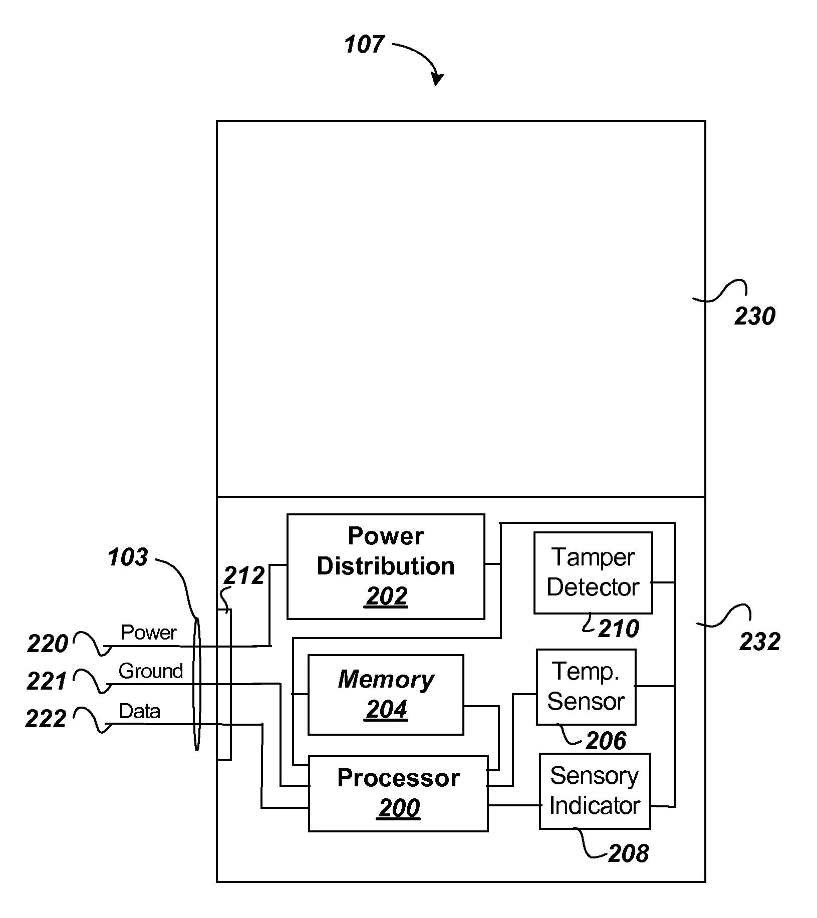
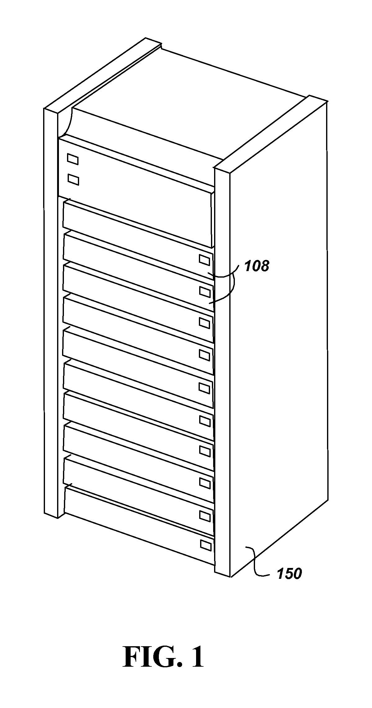
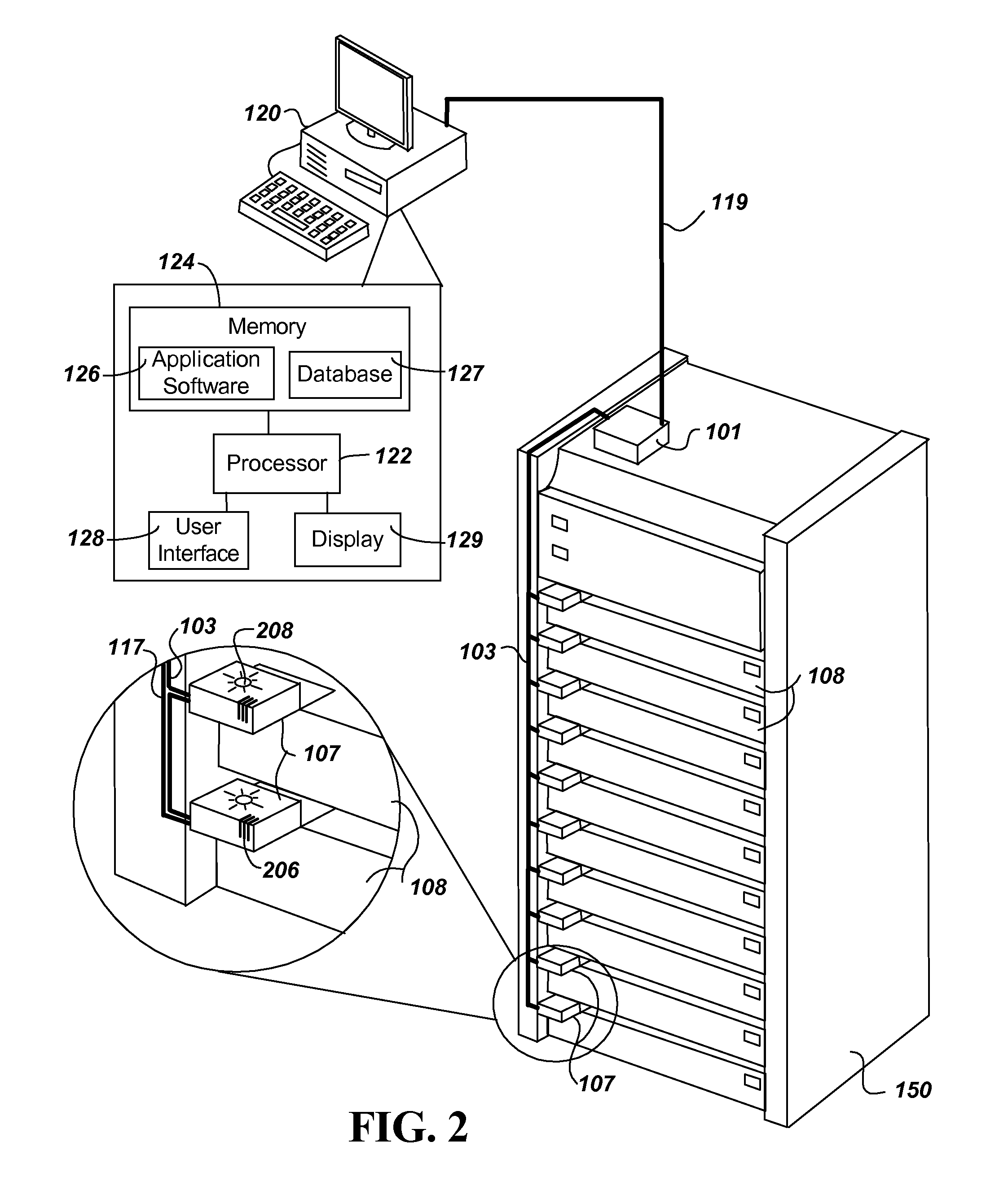
[0027]FIG. 2 shows components of a data center monitoring system according to embodiments of the present invention. The components shown include a single equipment rack (ER) 150 containing servers and / or other equipment rack equipment (ERE) 108. A single ER 150 is used for purposes of illustration only, as the system is intended for use with multiple ERs 150 typically found within a data center. The system further includes electronic ID tags (ET) 107, each being attached to an individual ERE 108. A communication and power data link cable (DL) 103 connects the ET 107s to an equipment rack controller (ERC) 101. The ERC 101 then provides a connection over a local area network 119 to a central control computer 120. The central control computer 120 contains a software application program 126 and database 127 to provide for monitoring, location and identification of each ET 107 in real time. Further, an ERC 101 can be attached to each ER 150 or to a group o...


PUM


Abstract

A data center equipment location system includes both hardware and software to provide for location, monitoring, security and identification of servers and other equipment in equipment racks. The system provides a wired alternative to the wireless RFID tag system by using electronic ID tags connected to each piece of equipment, each electronic ID tag connected directly by wires to a equipment rack controller on the equipment rack. The equipment rack controllers then link over a local area network to a central control computer. The central control computer provides an operator interface, and runs a software application program that communicates with the equipment rack controllers. The software application program of the central control computer stores IDs of the equipment rack controllers and each of its connected electronic ID tags in a database. The software application program in operation receives information from the electronic ID tags in real time enabling the central control computer to monitor the status, such as temperature and movement or tampering of each piece of equipment through its connected electronic ID tag. Further, the software application program can send a signal to an individual electronic ID tag to activate a sensory indicator to enable a technician(s) to locate a piece of equipment that is in need of repair or replacement.

Description

BACKGROUND[0001]1. Technical Field[0002]The present invention relates to a system for information technology (IT) asset location, monitoring, identification, and security. More particularly, the present invention relates to a system for location and identification of equipment in data center equipment racks, and for providing monitoring and security for the equipment.[0003]2. Related Art[0004]A data center is generally located in a high-tech building that is designed to run and operate large numbers of servers, computers and communication equipment. Data Centers are an essential element in the Internet and IT infrastructure of large organizations. There are thousands of data centers around the world, and an important component of any data center are the equipment racks that house the data center equipment, including servers, computers and communication equipment. A typical equipment rack can hold 40 to 50 standard sized servers or other pieces of equipment. FIG. 1 shows such an equi...

Claims


Application Information

Patent Timeline
Patent Type & Authority Applications(United States)
IPC IPC(8): G08B13/14G06F7/00
CPCG06Q10/087H04M15/49H04L41/12H04L43/0817G08B3/1083G08B21/182H04L12/14H04L12/1446H04L65/1016H04L65/1083H04M15/00H04W4/24H04M15/55H04M15/65H04M15/82H04M15/8228H04L12/12Y04S40/00H04L65/1095G08B5/36
Inventor GROTH, NOAHWARHUUS, JAN P.BOYADJIEV, KRASSIMIR ANASTASSOV
Owner ATTEND SYST
Why Eureka
Try Eureka