Apparatus for identifying and mounting printed circuit boards

a printed circuit board and mounting device technology, applied in the field of electronic components, can solve the problems of serious inefficiency on the assembly line, difficulty for a human or a machine installer to determine which holes correspond to the mounting pattern of a piece of equipment to be installed, and difficulty for a human or a computer installer to accomplish, so as to identify the mounting holes quickly and easily, and reduce the chance of errors

Inactive Publication Date: 2006-06-20
AMZETTA TECH LLC
View PDF8 Cites 0 Cited by
  • Summary
  • Abstract
  • Description
  • Claims
  • Application Information

AI Technical Summary

Benefits of technology

[0008]Embodiments of the present invention solve the above-described problems by providing a method and apparatus for mounting printed circuit boards or other electronic components that allow a human or machine installer to more easily identify the mounting holes corresponding to a particular hardware mounting pattern. Moreover, various embodiments of the present invention allow a human or machine installer to quickly and easily identify the locations for mounting hardware, thereby reducing the chances for error and improving installation efficiency.

Problems solved by technology

Although a universal mounting pattern allows many different types of equipment to be mounted within a rack-mount chassis, these universal mounting patterns may also cause difficulties.
In particular, the many different holes in the rack-mount chassis that comprise a universal mounting pattern may make it very difficult for a machine or a human installer to determine which holes correspond to the mounting pattern for a piece of equipment to be installed.
This can be difficult for a human or computer installer to accomplish.
The difficulty in locating the appropriate mounting holes for a particular piece of equipment can result in serious inefficiency on the assembly line and cause the assembly of a rack-mount chassis to be more expensive.
This is particularly true if a human assembler or a machine assembler accidentally places mounting hardware in the wrong holes.
This type of error may not be detected until the assembler actually tries to install the printed circuit board or other piece of equipment into the rack-mount chassis.
The reduced efficiency caused by such accidental misplacement of mounting hardware can become extremely expensive over time and substantially increase the manufacturing costs for the complete rack-mount chassis.

Method used


Image

  • Apparatus for identifying and mounting printed circuit boards
  • Apparatus for identifying and mounting printed circuit boards
  • Apparatus for identifying and mounting printed circuit boards

Examples


Embodiment Construction

[0025]In the following detailed description, reference is made to the accompanying drawings that form a part hereof, and in which is shown by way of illustration specific embodiments or examples. These embodiments may be combined, other embodiments may be utilized, and structural, logical, and electronic changes may be made without departing from the spirit and scope of the present invention. The following detailed description is, therefore, not to be taken in a limiting sense, and the scope of the present invention is defined by the appended claims and their equivalents.

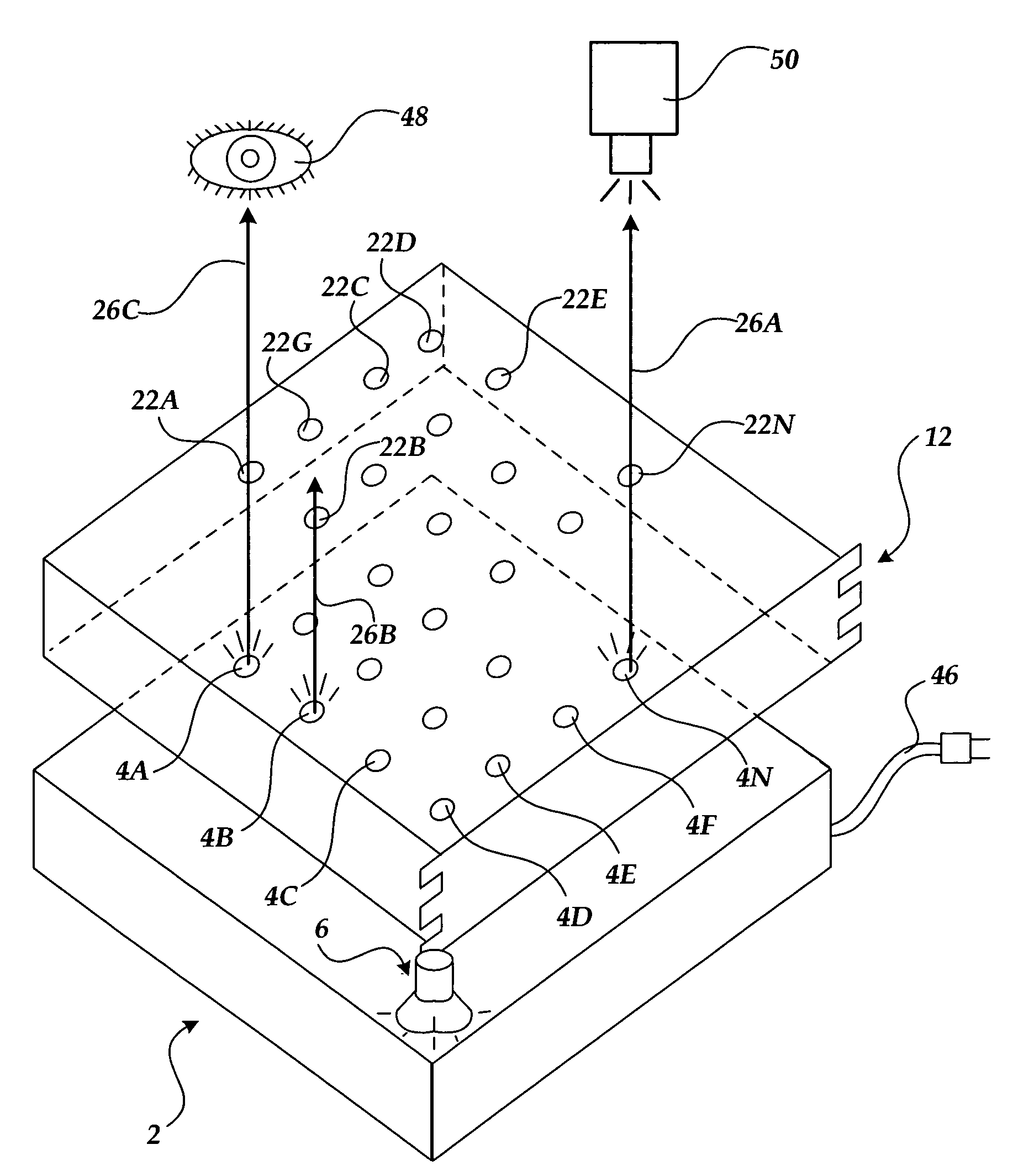
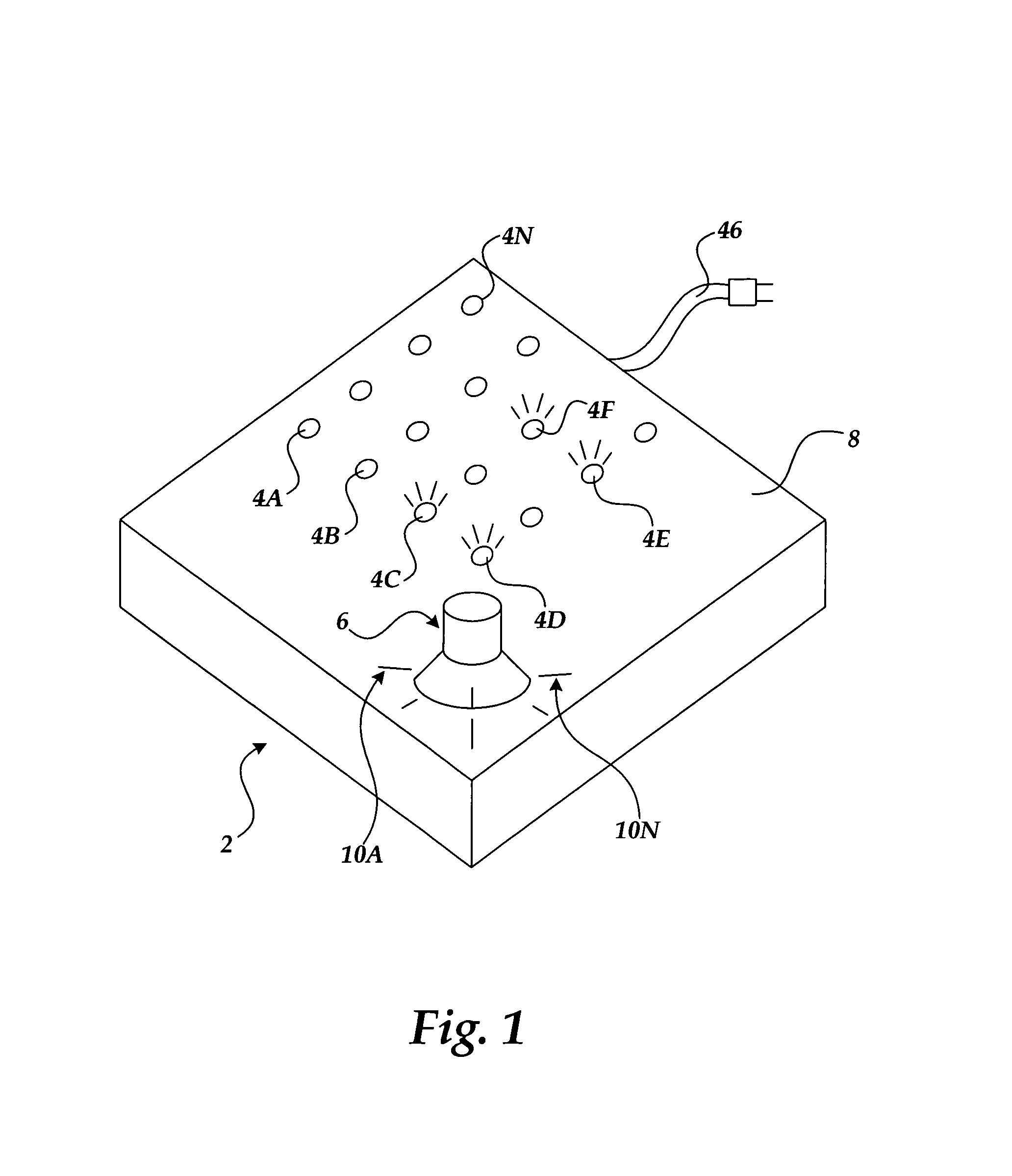
[0026]Referring now to FIG. 1, one illustrative embodiment of the present invention will be described. As shown in FIG. 1, an apparatus 2 is provided for assisting in the identification of mounting locations for mounting a printed circuit board or other type of electronic apparatus. As shown in FIG. 1, the apparatus 2 comprises a mounting surface 8 upon which one or more light sources 4A–4N may be mounted. The light...


PUM

PropertyMeasurementUnit
poweraaaaaaaaaa
rechargeable poweraaaaaaaaaa
timeaaaaaaaaaa

Abstract

An apparatus is provided for identifying one or more mounting locations for mounting a printed circuit board or other type of electronic device, including a mounting surface and one or more light sources mounted on the mounting surface. The light sources are located at positions corresponding to the mounting locations for mounting the printed circuit board or other type of electronic component. When illuminated, the light sources identify one or more mounting locations. The mounting locations are defined by mounting patterns corresponding to the mounting locations for a given type of printed circuit board or other electronic component. The light sources are illuminated so that only light sources corresponding to mounting locations defined by a particular mounting pattern are illuminated.

Description

TECHNICAL FIELD[0001]The present invention relates generally to the field of assembling electronic components and, more specifically, to the field of physically mounting printed circuit boards or other types of electronic components.BACKGROUND OF THE INVENTION[0002]Equipment racks are utilized to house a variety of different types of electronic equipment. For instance, a rack-mount chassis installed within a rack may be utilized to hold server computers, mass storage devices, telecommunications equipment, and a wide variety of other types of electronic equipment. The Electronic Industry Association's (“EIA”) standard EIA-310-D sets forth the standard dimensions and specifications for cabinets, racks, panels, and associated equipment utilized in standard-sized racks.[0003]In order to accommodate the many different types of equipment that may be mounted within a particular rack-mount chassis, the rack-mount chassis may have a large number of holes drilled in its bottom panel. These ho...

Claims


Application Information

Patent Timeline
Patent Type & Authority Patents(United States)
IPC IPC(8): B23P19/00H05K13/04H05K7/02
CPCH05K7/02Y10T29/5313Y10T29/53091Y10T29/4913Y10T29/53004
Inventor SIVERTSEN, CLAS GERHARD
Owner AMZETTA TECH LLC
Why Eureka
Try Eureka